- Welcome to Pulse Robot
- +86-23-63207381
- +8613677602178
- sales@pusirobot.com
Warning: key_exists() expects parameter 2 to be array, null given in /www/wwwroot/wordpress/wp-content/themes/betheme/functions/builder/class-mfn-builder-front.php on line 320
Warning: key_exists() expects parameter 2 to be array, null given in /www/wwwroot/wordpress/wp-content/themes/betheme/functions/builder/class-mfn-builder-front.php on line 343
Warning: key_exists() expects parameter 2 to be array, null given in /www/wwwroot/wordpress/wp-content/themes/betheme/functions/builder/class-mfn-builder-front.php on line 364
Warning: key_exists() expects parameter 2 to be array, null given in /www/wwwroot/wordpress/wp-content/themes/betheme/functions/builder/class-mfn-builder-front.php on line 370
Warning: key_exists() expects parameter 2 to be array, null given in /www/wwwroot/wordpress/wp-content/themes/betheme/functions/builder/class-mfn-builder-front.php on line 376
How does PLC control the stepper motor through CAN bus
Step 1: Material preparation
1. PLC: Delta DVP28SV11R2
2. CAN communication module: DVPCOPM-SL-CANopen
3. CAN bus integrated stepper motor: PMC007C6SEP 42-47
4. Computer
Step 2: Build the control network as shown below
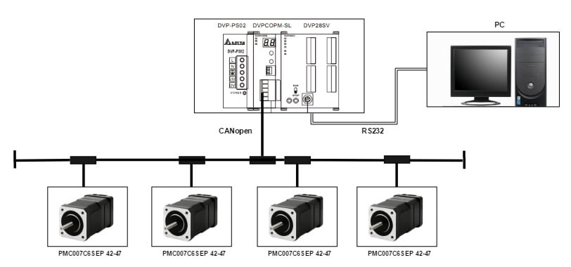
How PLC controls the network diagram of stepper motor through CAN bus
Step 3: CAN configuration
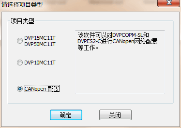
Open the CAN configuration software and select CANopen configuration
How PLC controls CAN configuration of stepper motor through CAN bus
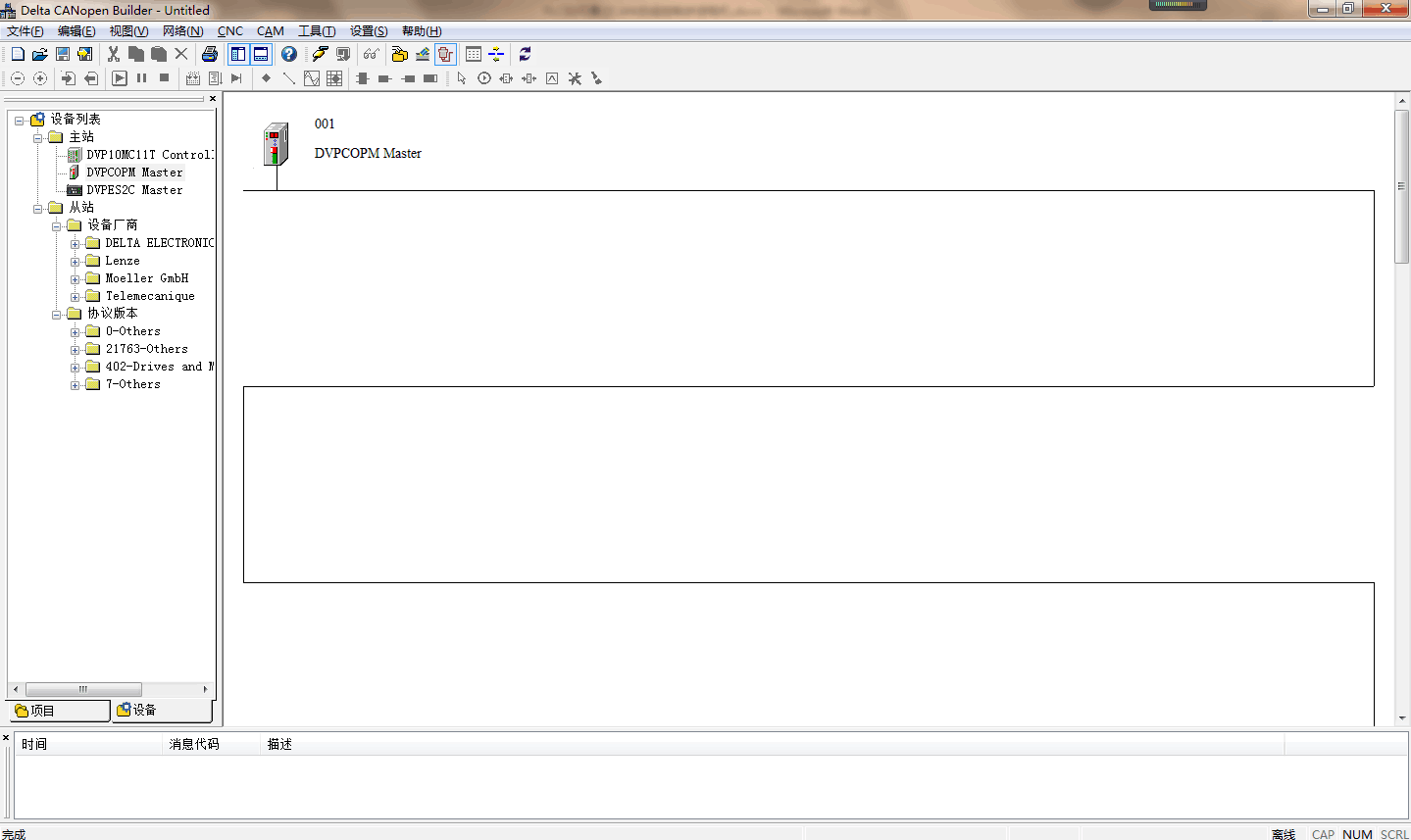
Select the device-master station-DVPCOPM Master
How does PLC control the stepper motor to add master station through CAN bus
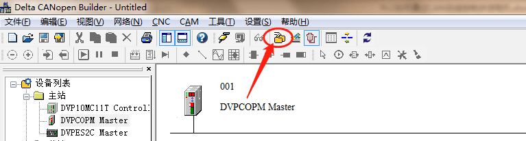
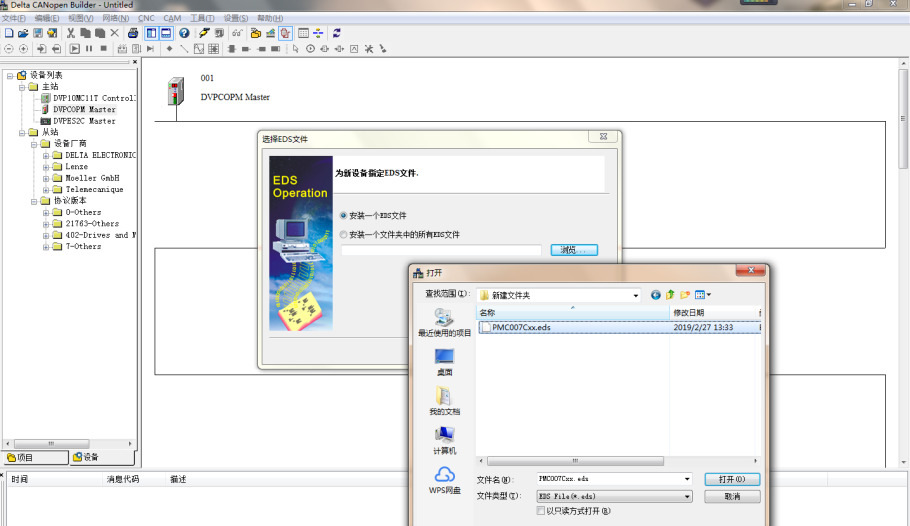
Select EDS operation
How PLC controls EDS configuration of stepper motor through CAN bus
Install EDS file—Next step—Install an EDS file—Browse and select the EDS file provided by PUSI manufacturer

How PLC controls the operation of stepper motor EDS through CAN bus

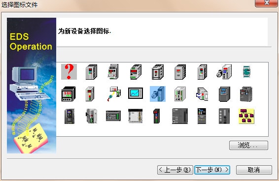
Install-select icon
Select icon
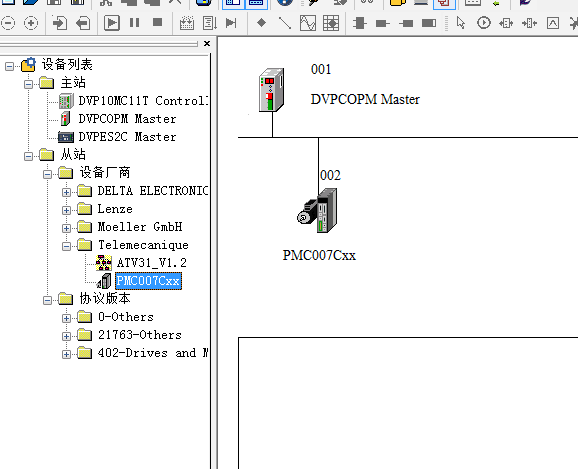
Slave station-equipment manufacturer-Telemecanuque-double-click PMC007xx to join the slave station, taking a configuration as an example:

Add Slave
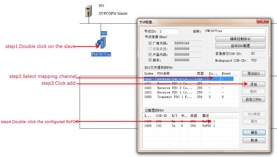
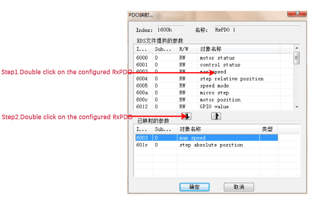
Slave configuration: Slave RxPDO configuration
Configure Slave
Add the mapping object 6003 to be configured as shown in the figure below, add 601c in the same step and click OK

Add mapping object
Slave configuration: Slave TxPDO configuration, follow RxPDO configuration to complete the following configuration
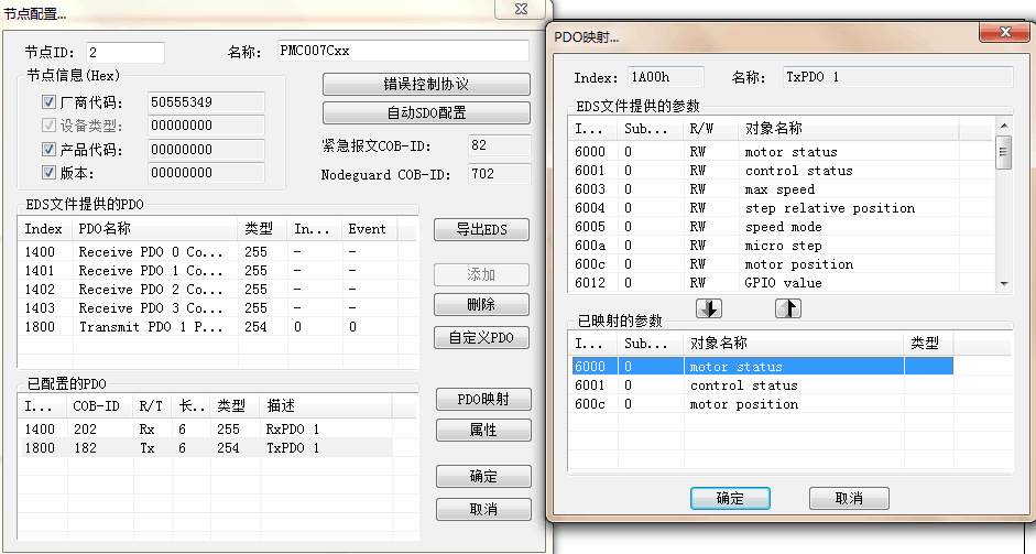
TxPDO configuration

Master station configuration: double-click the master station-click the configured slave station-click> join the configured master station
Master station configuration

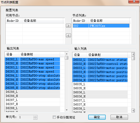
Complete the master-slave mapping configuration as shown below: here you need to pay attention to the master station address and slave station address, the settings on the device need to be the same as the addresses configured on the configuration software
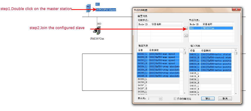
Group station configuration results
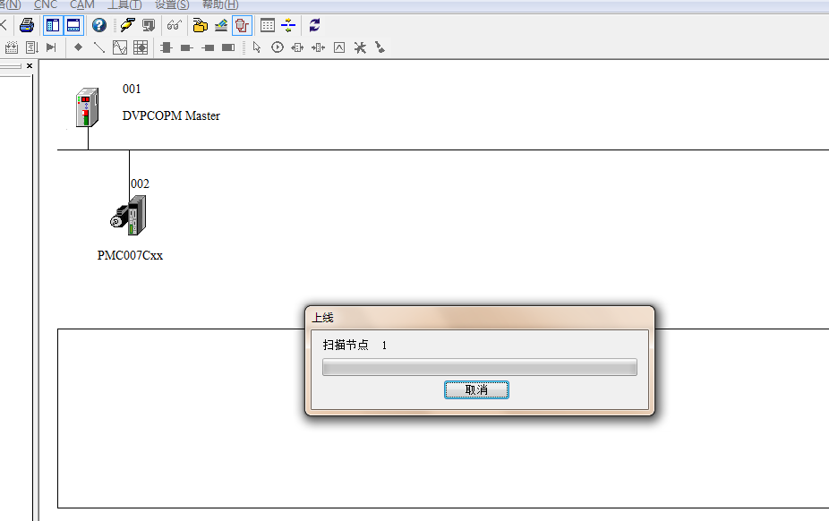
Click Online: If the device can be scanned, the wiring is correct, and the configuration of the master and slave is correct, then click Download to download the configuration into the CAN communication module

How PLC controls the online scanning of stepper motor network through CAN bus
The fourth step: PLC sends data to the slave station through PDO, and monitors the slave station to return data
Open the programming software: After online, create a monitoring table as shown below
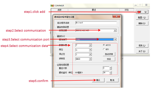
PLC communication port configuration
Open the programming software: After online, create a monitoring table as shown below
Create device monitoring table
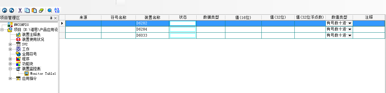
By writing values to the mapped speed address D6282 and position address D6284, the PLC can control the stepper motor through the PDO of the CAN bus
The above content is only the general configuration process. For other content related to the setting of the master station address and slave station address, please contact the manufacturer's technical engineer.