- Welcome to Pulse Robot
- +86-23-63207381
- +8613677602178
- sales@pusirobot.com
How to control stepper motor?
How to control a stepper motor: The simplest way is to use a mature stepper motor controller on the market.
CAN bus stepper motor drive controller
Five-axis stepper motor controller
PLC control stepper motor:
If it is necessary to position the rotation angle of the motor when controlling the motor, the stepper motor is a very suitable choice. The following is a detailed introduction to unipolar and bipolar stepper motors and how to control them from a microcontroller.
Unipolar stepper motor
The unipolar stepper motor has five or six wires. The five-wire version has four coils, all of which are connected to one electrode. The six-wire motor is actually bipolar, with the two coils separated by the center connection of each coil. The center connections of the coils are tied together as shown in Figure 1 and used as a power connection. They are called unipolar steppers because electricity is always at this pole.
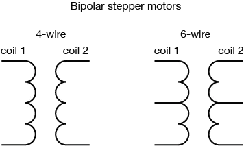
Figure 1. Wiring of a unipolar stepper motor, the center lines of two coils are tied together in a unipolar stepper
Bipolar stepper motor
The bipolar stepper motor usually has four wires coming out of it. Unlike unipolar steppers, bipolar steppers have no common connection. They have two sets of independent coils, as shown in Figure 2. By measuring the resistance between the wires, you can distinguish them from unipolar stepper motors. You should find two pairs of wires with equal resistance. On a coil), you will see infinite resistance, or no continuity. Some bipolar stepper motors have a center connection on each coil. These central connections can be connected to turn a 6-wire bipolar stepper motor into a unipolar stepper motor.
Figure 2. Wiring of bipolar stepper motor
Like other motors, stepper motors require more power than microcontrollers can provide, so a separate power supply is required. Ideally, you can get the voltage from the manufacturer, but if you do n’t know, please use a variable DC power supply, apply a minimum voltage (hopefully about 3V), on the two wires of the coil (such as 1 to 2 or 3 to 4) Apply voltage to it, then slowly increase the voltage until the motor is difficult to turn. This may damage the engine, so you cannot test too high a voltage. Typical voltages for stepper motors may be 5 volts, 9 volts, 12 volts, 24 volts. Higher than 24 volts is not very common for small stepper motors. Frankly speaking, it is best not to test above this level. How to control stepper motor
H-bridge control of stepper motor
To control stepper motors, both types of stepper motors can be controlled with an H-bridge by applying voltage to each coil in a specific order. The sequence is as follows:
The circuit for controlling the unipolar stepper or bipolar stepper from the h-bridge is very similar. In both cases, the four ends of the coil are connected to the four outputs of the H-bridge. The difference is that for unipolars, there is also a common centerline. This wire can be connected to the same motor voltage source that powers the H-bridge, or it can remain off. If you do the latter, treat the unipolar motor as if it had two independent coils, in other words, as if it were a bipolar stepper motor.
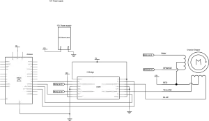
Figures 3 and 4 show the wiring from the unipolar stepper motor to the H-bridge:
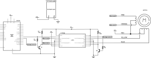
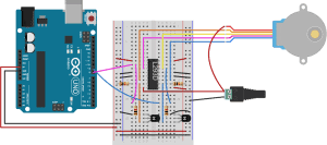
Figure 3 Schematic diagram of a unipolar stepper motor connected to H-bridge and Arduino. Figure 4. Lateral view of a unipolar motor connected to H-bridge and Arduino.
Please note that the center pole is connected to the 12V power supply and the H-bridge, and it is also possible to run a unipolar stepper motor without connecting the center pole in this way. If you do this, it basically acts as a bipolar stepper.
To control a bipolar stepper motor, use the same stepping as the unipolar stepper motor to supply the coil current, but instead of using four coils, use two poles of the two coils and reverse the polarity of the current between the coils Figures 5 show this circuit. The circuits of unipolar motors and bipolar motors are the same, except for the centerline of unipolar motors:
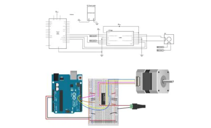
Figure 5 Schematic diagram of bipolar stepper motor connected to H-bridge and Arduino. Figure 6. Experimental board of bipolar stepper motor connected to H-bridge and Arduino.
Once there is a stepper motor in one direction, it is a simple matter to do the stepping in the other direction, just do it in the reverse order.
To know the position is to know how many degrees each step has, and then calculate the degree of each step, and then multiply this degree. For example, if you have a 1.8-degree stepper motor, it rotates 200 steps, which is 1.8x 200 degrees, which is 360 degrees, which is a full circle.
Two-wire controlAt each step of the sequence, the two wires are always set to opposite polarities. Therefore, with a slightly more complicated circuit, only two wires instead of four can be used to control the stepper motor. By using npn transistors on each pair of wires, the other pair of wires can be turned off while one pair of wires is energized. The base of the transistor is connected to the first pin and the output pin of the microcontroller through a 1 kiloohm resistor. The second pin is connected to + 5V through a 10 kohm pull-up resistor, and the collector of the transistor is also connected to this pin. The emitter of the transistor is grounded. When the transistor is turned on, it provides a path with the least resistance to ground for the current through the pull-up resistor, while grounding the second H-bridge pin. Therefore, pulling the output pin of the microcontroller causes the first H-bridge pin to rise simultaneously and the second pin to fall simultaneously. Copy this circuit for the third and fourth pins O
The two-wire stepping circuit is shown in Figure 6. The circuits of unipolar motors and bipolar motors are the same, except for the centerline of unipolar motors:

Figure 7. Schematic diagram of a unipolar stepper motor, connected to H-bridge and Arduino, in a two-wire configuration. Figure 8. Experimental board view of an L293D H-bridge connected to Arduino, used to drive a stepper motor, 2-wire
The bipolar stepping two-wire circuit is shown in Figure 7:

Figure 9. Schematic diagram of bipolar stepper motor connected to H-bridge and Arduino two-wire version. Figure 10. Experimental board diagram of bipolar stepper motor connected to H-bridge and Arduino 2-wire structure.
The step sequence is the same as the step sequence of the above two middle conductors:
Step wire 1 wire 2
1 low high
2 high high
3 high low
4 low low
Singlechip programming and controlling stepper motor
Since both the unipolar stepper motor and the bipolar stepper motor are controlled by the same step sequence, similar code can be used for any configuration in the Arduino stepper motor controller, and only the initial pin configuration needs to be changed. For more information on programming stepper motor control, please refer to: Microcontroller Controlling Stepper Motors
How to control a stepper motor: The simplest way is to use a mature stepper motor controller on the market