- Welcome to Pulse Robot
- +86-23-63207381
- +8613677602178
- sales@pusirobot.com
Application examples of liquid level detection in IVD equipment
Liquid level detection has almost become a necessary function in the field of fully automatic medical equipment. In the process of sample addition and pipetting of fully automatic medical equipment, it is necessary to detect whether the probe touches the liquid surface of the reagent, use this as the basis for the equipment system enter to next step. In order to improve the detection speed, most of the current IVD instruments use multi-channel liquid level detection to improve the efficiency of the system. The liquid level detection function of the equipment will be used thousands of times in the daily work. Once the liquid level detection has any deviation there will be abnormal operating conditions of equipment such as firing needles and reagent cross-contamination. How to ensure the orderly, stable and efficient work of multi-channel liquid level detection has also become a focus and difficulty of the research and development personnel of fully automatic medical equipment.
In the article《Medical equipment liquid level detection solution: capacitive liquid level sensor controller》,the difference and several advantages of the capacitive liquid level sensor controller PCS0902 compared to the traditional liquid level detection scheme have been introduced in detail, which has been recognized by the majority of IVD equipment manufacturers. From the manufacturer’s sample to the mass production of the equipment, we have received many engineers’ questions about the use of the PCS0902 liquid level detection module. These questions are similar. This article will combine a certain IVD equipment manufacturer from getting the module to the final successful mass production. Successful application examples, analysis and answers to some common problems.
This project example is an application example of reagent level detection of a fully automatic immunoassay equipment. The article will start with the unsatisfactory effect of the initial experiment and describe the whole process to the final expected effect.
Initial test:
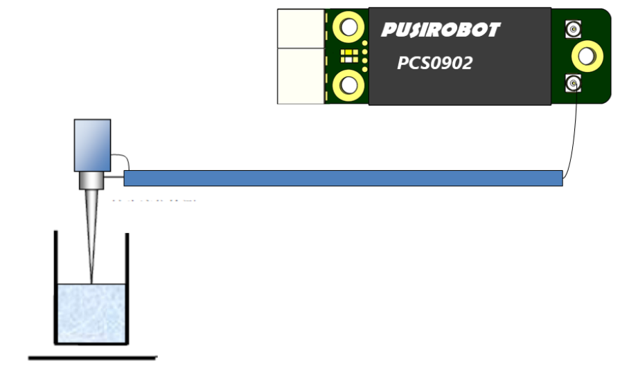
Test method and tools: PCS0902 capacitive liquid level detection module single-ended mode 1 is used for detection, the cable core wire is connected to a single-layer probe, and the PUSICAN tool software of PISIROBOT company is run on the host computer for real-time waveform monitoring.
Detection diagram:
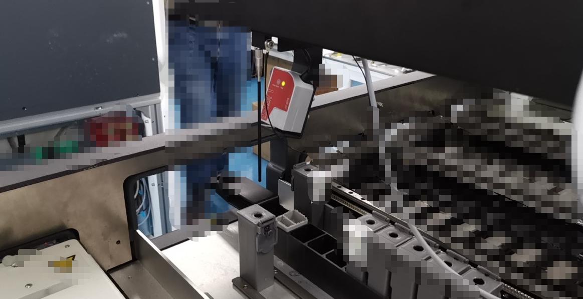
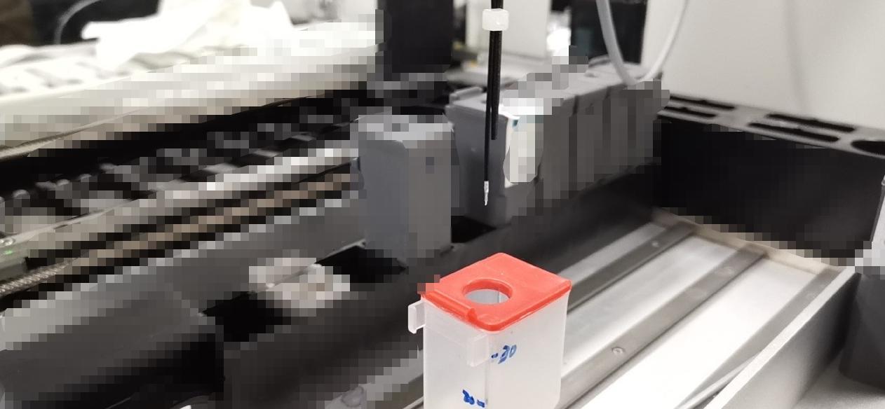
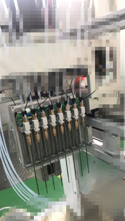
Experimental environment diagram:
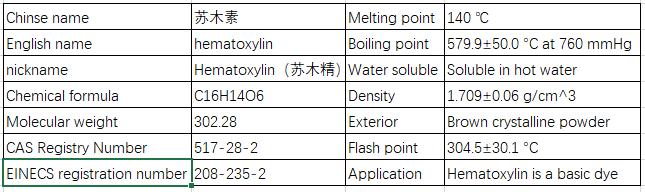
Experimental reagent: hematoxylin
Hematoxylin is a staining agent extracted from Hematoxylin. It is oxidized to produce hematoxylin. It is used together with mordant (commonly used is trivalent iron or aluminum salt) to stain cell nuclei. Hematoxylin is a basic dye.
characteristic:
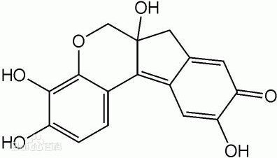
Molecular Structure:
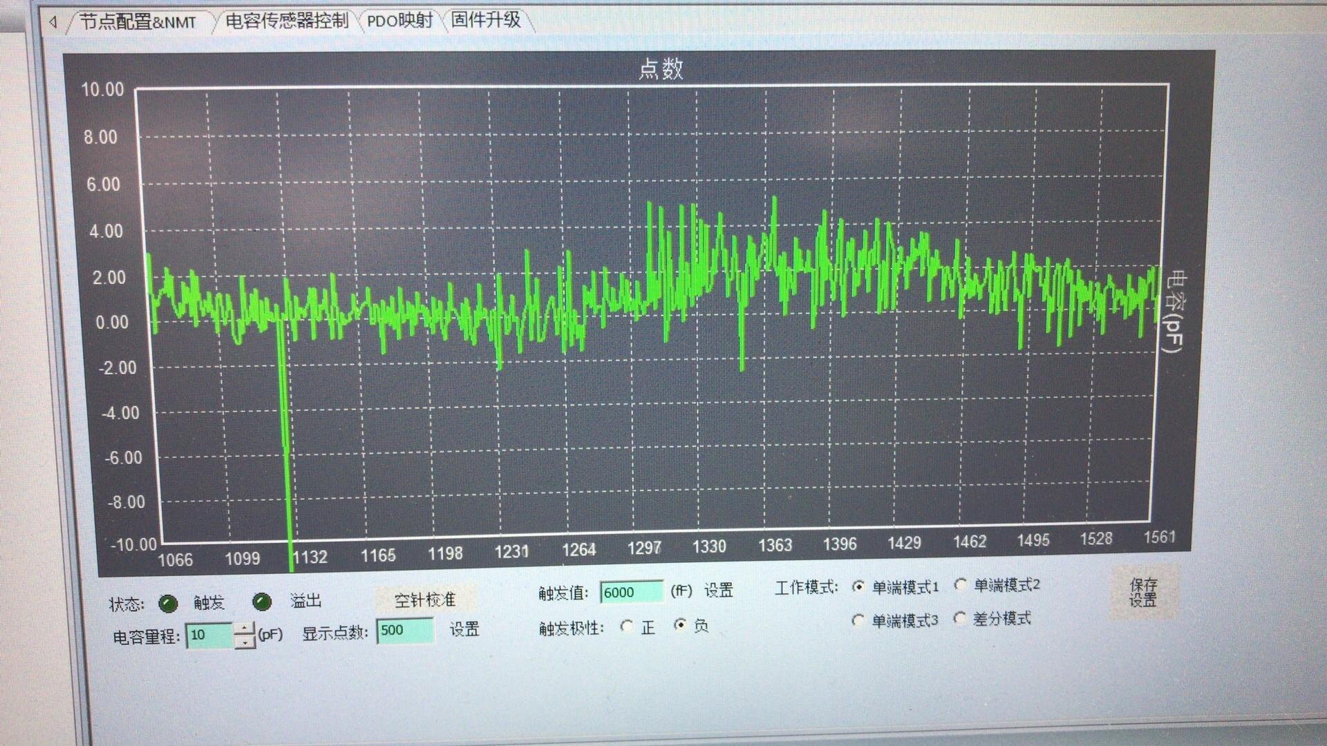
After the equipment is set up, the detection curve of the capacitance value of the empty needle after the initial startup: the capacitance value fluctuates greatly and is not at the zero line.
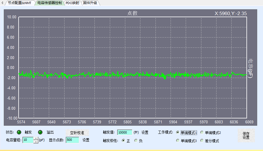
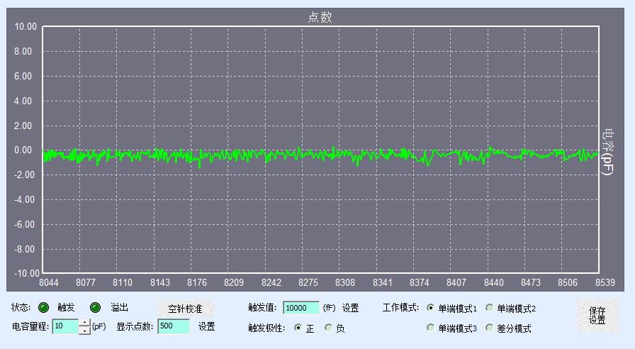
Click the empty needle to calibrate the capacitance value detection curve of the empty needle situation: the capacitance value returns to near the zero line, but the fluctuation is still large.
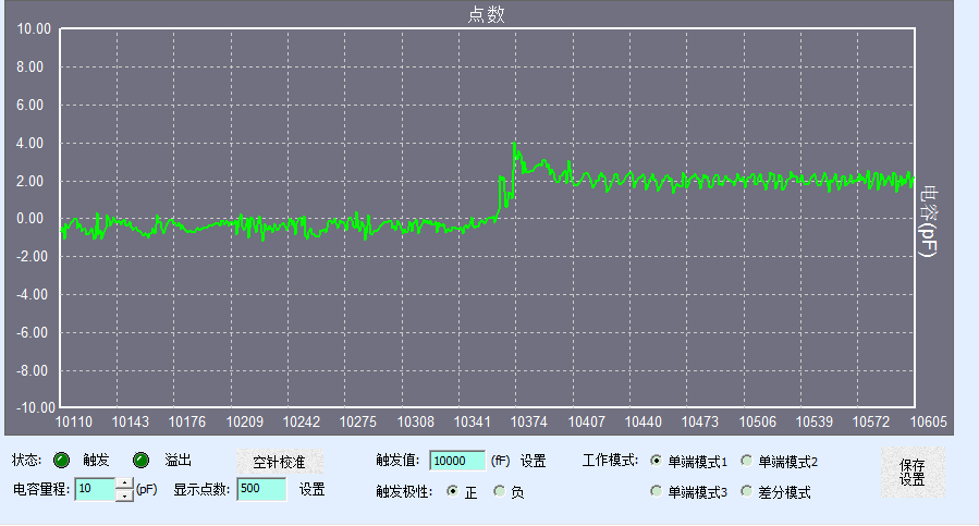
The change of capacitance value curve when the detection reagent is hematoxylin: the capacitance value changes very little, only about 2pF.
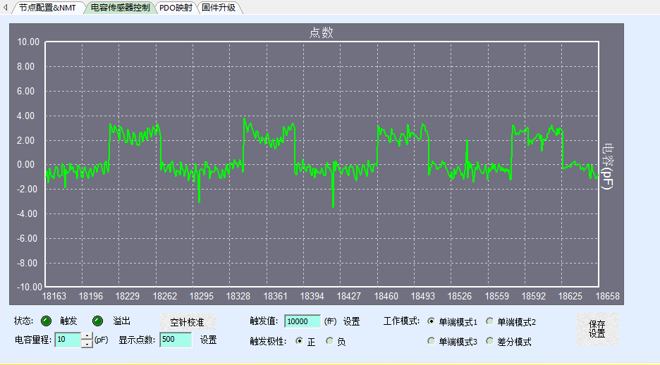
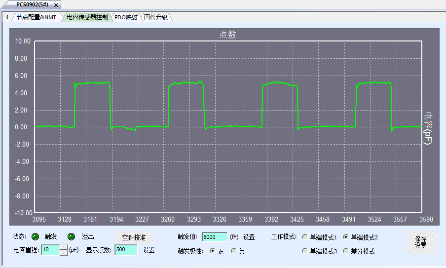
Repeated detection of hematoxylin reagent, capacitance value change curve:
The results of the initial experiment were not ideal. In addition to the problems described above, there were some other problems, but after analysis and improvement, the ideal detection waveform as shown in the figure below was finally obtained to realize the mass application of the product on the equipment. From the very unsatisfactory initial test results to the final expected results, we have summarized the following main influencing factors, and the improvement process is detailed below.
Factor 1. The influence of module power supply on the detection value:
In experiment 1, only the 5V power supply port of the main board of the device was used to power the liquid level module, and the empty needle detection waveform obtained after the empty needle was aligned is as follows:
It can be seen that the capacitance detection value fluctuates greatly when the needle is empty, and the detection value is unstable.
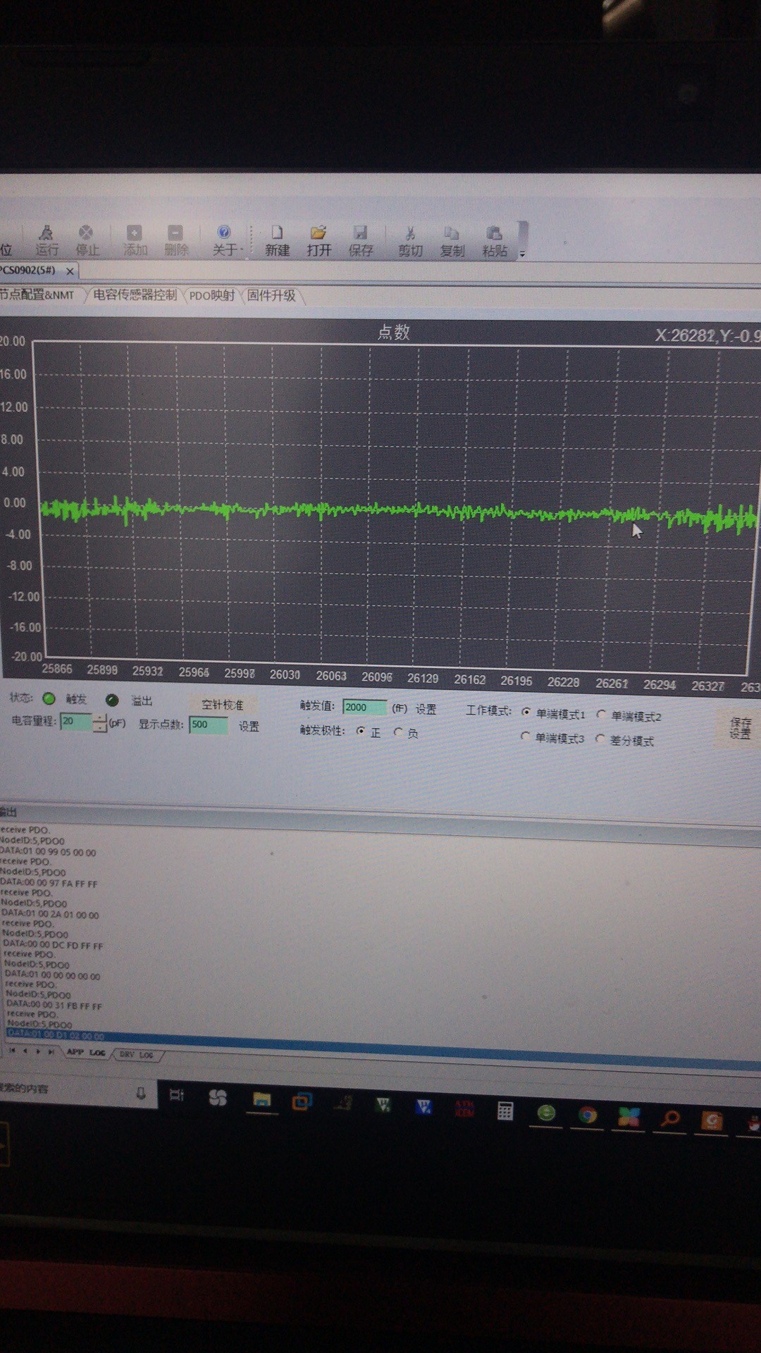
Improvement method: Separate the module power supply from other system components and change it to a standard single regulated 5V power supply. Treat the PCS0902 module power supply ground, equipment power supply ground and equipment rack ground to the same ground, and then obtain the empty needle detection value, the waveform is as follows:
The comparison of the two figures shows that the fluctuation of the empty needle detection value is significantly reduced.
Another customer used a low-quality 5V switching power supply during the test, and contacted the shielding layer with the metal frame. The capacitor waveform seen after power-on can no longer be described by ripple.
In order to compare the degree of influence of the power supply, the comparison waveform after the customer uses a pure power supply (battery power supply) is as follows:
Regarding the connection of the shield signal, we can analyze it from the internal signal diagram of the PCS0902 capacitive detection module:
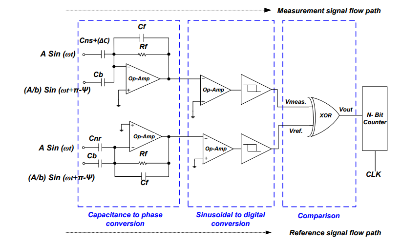
This figure shows the outer shielding signal and core signal of the module. From this schematic diagram, we can know that when using the module, it is not a simple grounding of the outer shielding signal, nor grounding between the shielding layers, but the chassis grounding.:
Factor 2, the influence of the fixed material of the sample needle on the detection value.
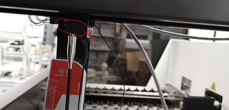
The red circle in the above figure is experiment one. The single-layer probe fixed base is made of POM. The dielectric constant of this fixed material is relatively high, which will cause large fluctuations in the capacitance detection value and high basic capacitance. It is recommended to use poly Imide is used as the probe fixing material.
Dielectric constant is also called permittivity or relative permittivity, an important data that characterizes the electrical properties of dielectrics or insulating materials, and is often represented by ε. It refers to the ratio of the capacitance when the same substance is used as the dielectric and the vacuum in the same capacitor, and indicates the relative ability of the dielectric to store electrostatic energy in the electric field. The epsilon value of air and CS2 are about 1.0006 and 2.6 respectively, while the epsilon value of water is larger, 83.83 at 10°C.
According to the dielectric constant of the substance, the polarity of the polymer material can be judged. Generally, substances with a relative permittivity greater than 3.6 are polar substances; substances with a relative permittivity in the range of 2.8 to 3.6 are weakly polar substances; substances with a relative permittivity less than 2.8 are non-polar substances.
In the same way, we can also roughly estimate the dielectric constant of the material based on the polarity of the polymer material. There are many polar groups, high dielectric constant, few polar groups, and low dielectric constant.
The following are the dielectric constants of common insulating materials:


When using the PCS0902 liquid level detection module with the probe to detect the capacitance value of the reagent, it is necessary to select an insulating material with the smallest dielectric constant as the fixing material between the probe and the metal frame.
Factor 3, the influence of probe type on capacitance detection value
Other conditions are the same, without using a probe, directly use the coaxial cable provided by Specs to replace the probe. The core wire of the cable contacts the liquid surface as shown in the figure:
The detection waveform is as follows: the detection waveform is very stable
Using a double-layer probe with shielding layer, the detection waveform is as follows:
Using a single-layer probe without shielding layer, the detection waveform is as follows:
From the waveform comparison, it can be seen that the signal detection value is the most stable when the probe is directly used for detection with the coaxial cable. When the double-layer probe and the single-layer probe are used, the detection effect decreases sequentially. During the transmission of the detection signal from the detection terminal to the PCS0902 module, the shielding protection of the detection signal is particularly important. Therefore, it is recommended that equipment manufacturers use double-layer probes with shielding layer and minimize the transmission distance of detection signals to avoid unnecessary signal interference.
Factor 4, When there is liquid in the system pipeline (mainly refers to the cleaning fluid or other liquid inside the probe and the back-end pipeline connected with the probe),whether the probe pipeline and the back-end pipeline of the probe are disconnected by a valve. Influence of capacitance detection value
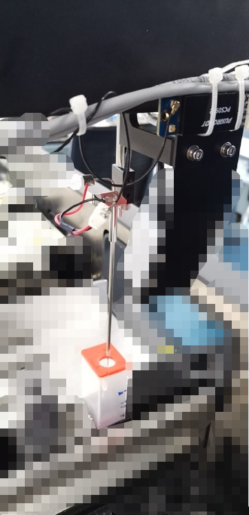
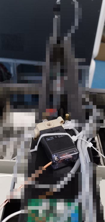
Fill the pipeline with cleaning liquid, connect a double-layer shielded probe, and add a solenoid valve between the probe pipeline and the back-end liquid circuit to control the on-off of the liquid circuit. The installation of the probe and the solenoid valve is as follows:
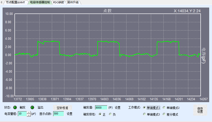
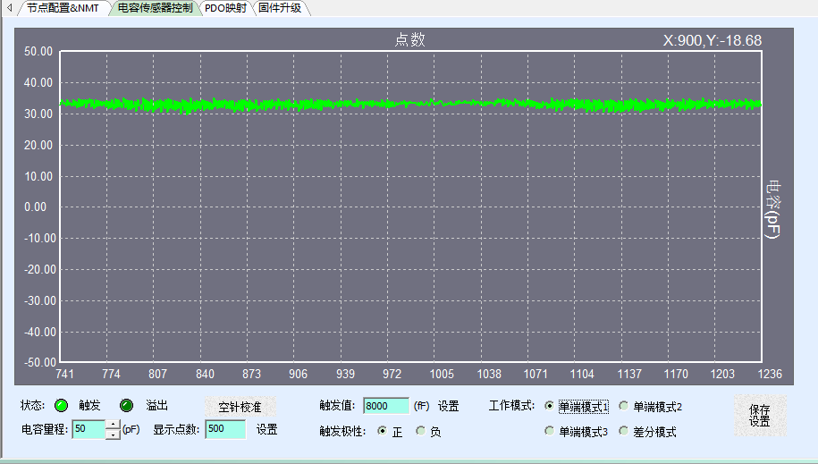
When the solenoid valve is opened and the probe fluid path is connected to the back- fluid path, the measured waveform is as follows: the empty needle signal is about 33pf, and the signal variation amplitude is 4pf
When the solenoid valve is closed and the front fluid path and the back-fluid path are cut off, the detection value waveform is as follows.f
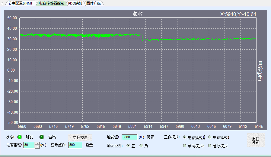
From the comparison of the two figures, it can be seen that after the system pipeline is filled with liquid, whether the liquid path at the front end of the probe is connected to the back end of the probe has a great influence on the capacitance detection value. The main reason for this phenomenon is the conductive ions in the liquid (there are conductive ions in most cleaning liquids), which causes the probe and the back end of the system to be connected together, which seriously affects the capacitance detection value.
Factor 5, When the front fluid path of the probe is connected to the rear fluid path, whether there is an air column between the cleaning fluid and the detection fluid in the front fluid path of the probe affects the detection value.
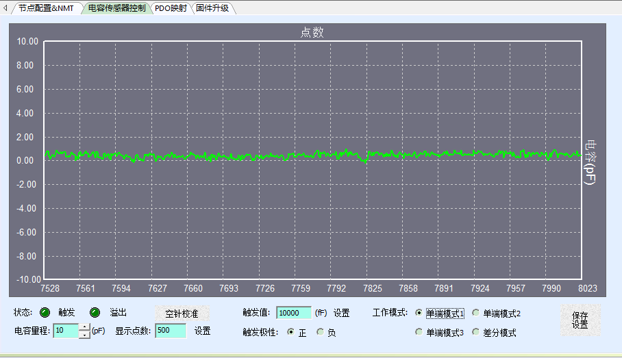
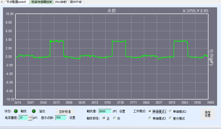
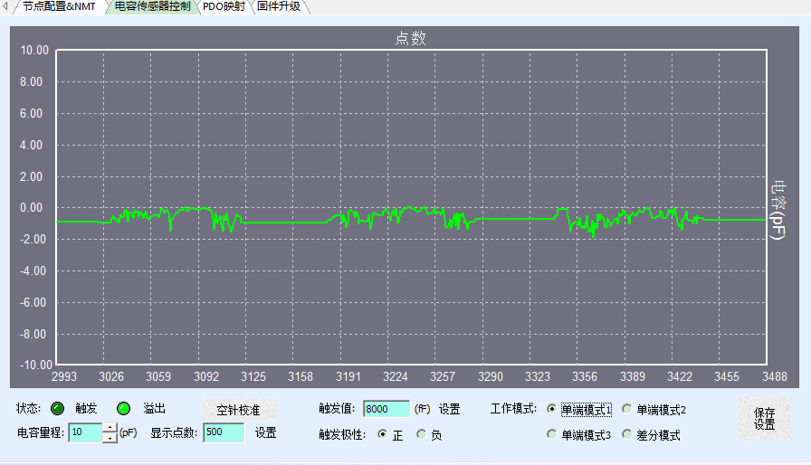
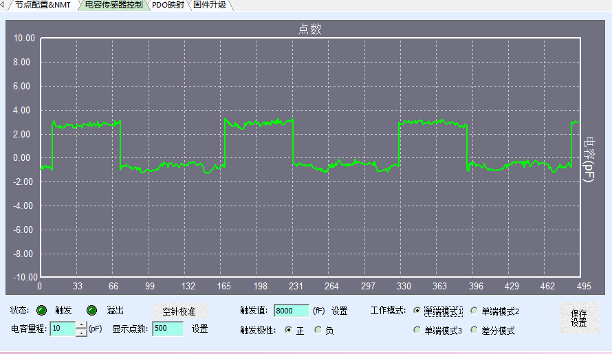
The solenoid valve is closed, the front fluid path is disconnected from the rear fluid path, and there is no air column disconnection between the cleaning fluid and the detection fluid in the front fluid path of the probe, and the reagent is detected. The detection value waveform is as follows: reagent detection value and empty Needle detection value cannot be distinguished
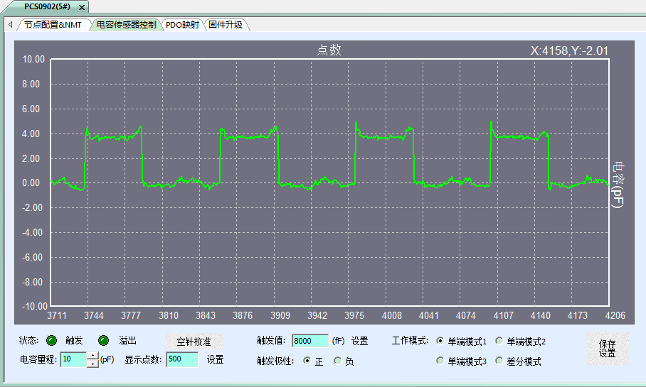
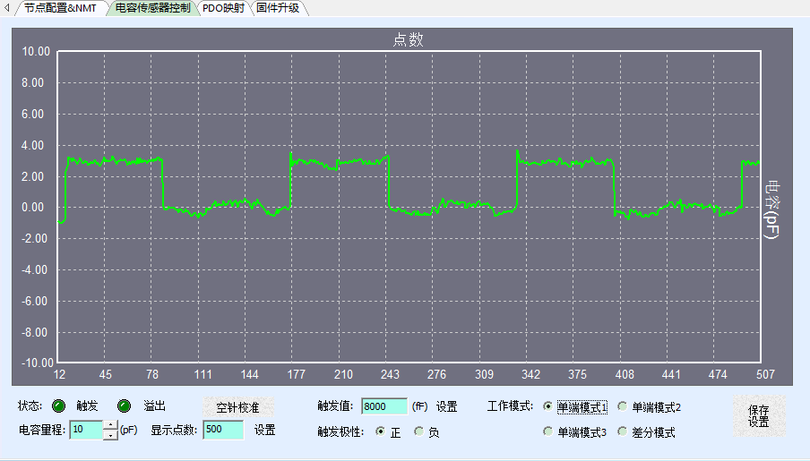
The solenoid valve is closed, and the front fluid path is disconnected from the back- fluid path. In the front fluid path of the probe, there is a 200ml air column between the cleaning solution and the detection solution to detect the reagent. The detection value waveform is as follows: reagent detection value and empty needle Detection value can be distinguished.
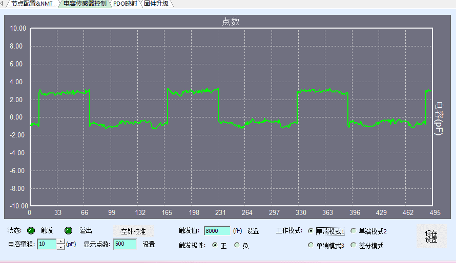
The comparison of the two figures shows that when the solenoid valve is closed and the front-end fluid path of the system is disconnected from the back-end fluid path, whether there is an air column in the front-end fluid path blocking the cleaning fluid and the detection reagent, which has a great impact on the detection value. Air column blocking detection effect will be much better, this kind of waveform will eventually meet the equipment requirements.
Therefore, when using the capacitive liquid level sensor controller PCS0902 with a probe to detect reagents, you must first design a reasonable detection process. A successful detection process is recommended as a reference (different equipment may have subtle differences):
1、Open the valve, introduce the cleaning fluid, and rinse the probe.
2、Keep the valve open and suck a fixed volume of air to facilitate the formation of an air column between the subsequent test liquid and prevent liquid mixing. This volume is generally 20uL.;
3、Close the valve and cut off the connection to the back-end cleaning solution pool. This step is to prevent a large amount of back-end cleaning solution from affecting the test capacitance value of the probe front end, because the cleaning solution is charged ions.
4、Empty needle calibration.
5、Absorb the test liquid and test the capacitance value.
6、After the test liquid is completed, put the test liquid into the reaction tube, then open the valve to clean the probe with the cleaning liquid.
7、Repeat the above steps for the second test, but at this time you can subtract the empty needle calibration link, because the capacitance value of the remaining cleaning solution at the tip of the second probe is basically the same as the first one, so the tip of the probe The length L between the valves should be as small as possible, and the smaller the test, the smaller the drift.
Factor 6, The influence of high-power interference source on capacitance detection value
Among the many problems reported by customers, we have also found that high-power devices affect the detection value.
The experimental environment is as follows:
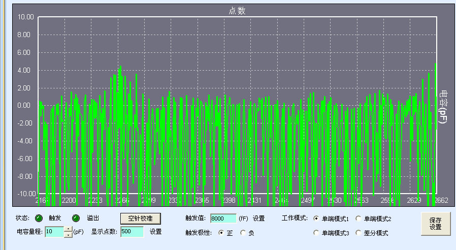
When the high-power pump is working, the waveform measured by the empty needle is as follows:
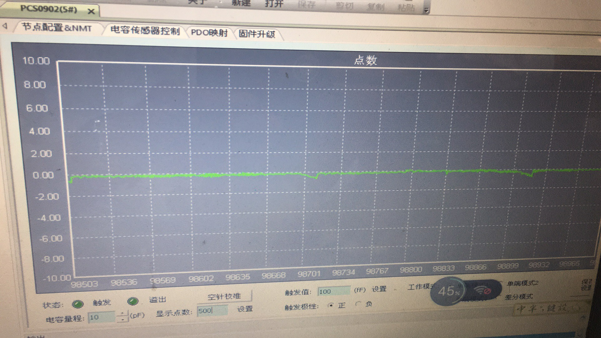
The customer changed a number of liquid level detection modules and probe connection methods, but they were unable to effectively remove this strong interference. Finally, with the assistance of PUSIROBOT’s engineers, the customer modified the filter parameters of the PCS0902 module to set the specific frequency of the interference signal After filtering out and updating the firmware, when the high-power pump is working, the empty needle detection waveform is as follows:
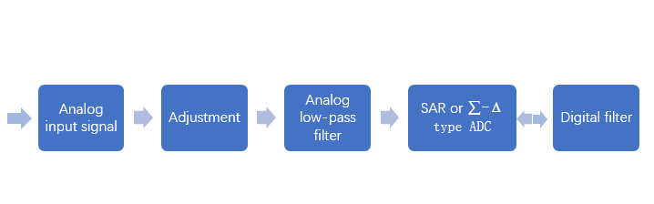
It can be seen from the waveform diagram that after modifying the firmware filter parameters, the interference is significantly reduced. This case reflects the algorithm flexibility of the PCS0902 capacitance detection module. Unlike some solutions that use integrated liquid level chips, PCS0902 is based on pure software algorithms, as shown below
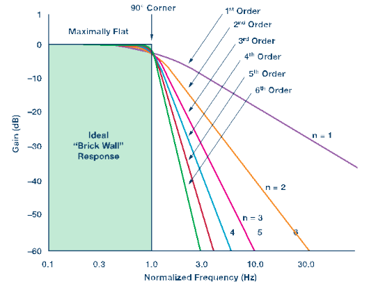
Therefore, in this case, the filter parameters can be adjusted and modified according to the customer's actual rack distributed capacitance and inherent interference characteristics, so as to obtain a unique detection effect. The engineer first obtains the interference frequency characteristics of the equipment through the pusican tool. Then modify the parameters accordingly, and finally obtain the ideal detection waveform.
The digital filter signal diagram is as follows:
Factor 7, The influence of different detection reagents on capacitance detection value
In the case of avoiding the above five factors that may cause problems, the waveforms obtained by detecting the same volume of different reagents are as follows:
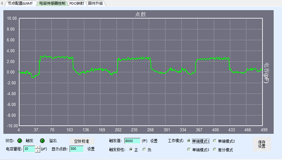
When the detection reagent is the primary antibody, the waveform is as follows:
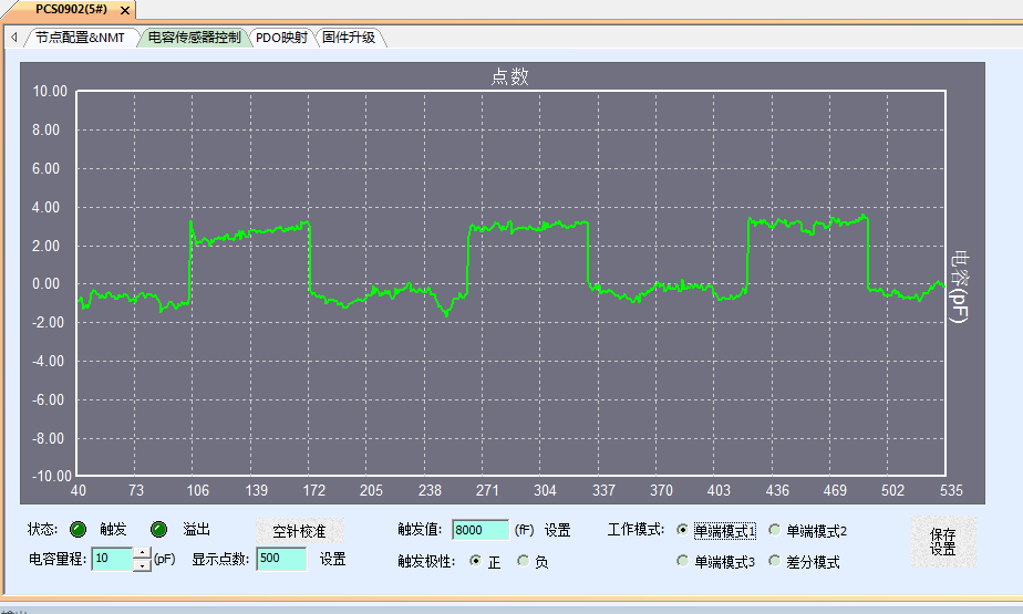
The detection reagent is hematoxylin and the waveform is as follows:
When the detection reagent is DAB diluent, the waveform is as follows:
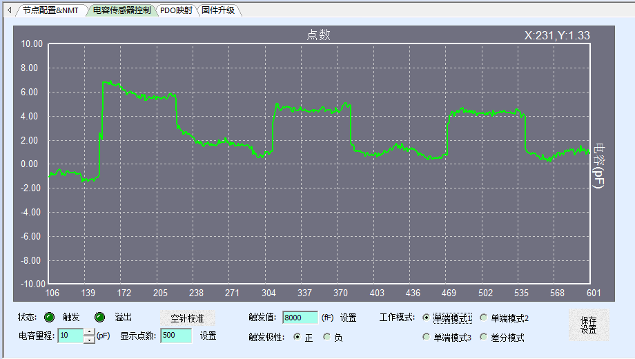
When the detection reagent is DAB diluent, the waveform is as follows:
When the detection reagent is DAB concentrate, the waveform is as follows:
When the detection reagent is an enhancer, the waveform is as follows:
It can be seen from the figure that the detection waveforms obtained by different reagents will be different. The main reason is that different reagents have different dielectric constants. The higher the dielectric constant value, the easier it is to be detected.