- Welcome to Pulse Robot
- +86-23-63207381
- +8613677602178
- sales@pusirobot.com
Introduction to the application scenarios of PUSIROBOT integrated closed-loop stepper motor
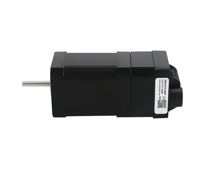
The PMC007 stepper motor combination unit packs the controller, stepper motor driver and motor in a compact package.
Controller and stepper motor driver: Eliminate the wiring between the controller and stepper motor driver. The unit receives instructions directly from the PLC and can be used in conjunction with various stepping motors. The combination of controller and stepper motor driver is a good choice for motion control applications involving stepper motor control of multiple axes, because there are some versions on the market that can handle motion control of up to six axes.
Drives and motors: Remove the stepper motor drive from the cabinet, thereby reducing the space required and the amount of heat generated. This results in a smaller enclosure and may eliminate cooling components such as fans, heat exchangers and air conditioners. High-volume applications can get the most benefit from the motor/drive combination because it simplifies the design without compromising performance. It also reduces the total cost and ensures component compatibility. Some suppliers provide these combination units in industry standard motor frame sizes, such as NEMA 17 or 23.
Controller, driver and motor: This fully integrated stepping motion system eliminates the cable connection between the controller, driver and motor. By removing the controller and drive from the chassis, you can minimize chassis space and heat generation. It is the most compact and cheapest option among the three combination units.
PLC /stepper motor communication
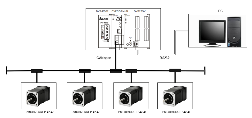
Whether you choose individual components or combined units, you still need a PLC or PC to provide supervisory control and coordination. Most stepper motors are paired with PLCs, and we will now study the design in detail.
Automated machines and processes are usually controlled by PLC. In addition to real-time control, PLC also coordinates all controlled equipment, such as motors, valves and cylinders, and provides functions including data collection and storage and remote access. The interface between PLC and stepper motor controller can either be hard-wired between the two through separate inputs and outputs, or through digital data links. Hard-wired signals require a lot of wiring and corresponding installation work, which opens up the possibility of wiring errors.
Digital data links such as the Ethernet protocol Modbus TCP require only a single cable between the PLC and the stepper motor controller to simplify installation. Several stepper motor controllers can be connected to the Ethernet, thereby further reducing wiring.
Digital communication is more flexible, and new functions can be added by just reprogramming the PLC and stepper motor controller without running new wires. The full range of stepper motor controller functions, including control, monitoring and diagnostics, are usually available via a digital data link (all via an Ethernet cable). Simplify PLC programming
The PLC must be programmed to command the stepper motor controller, which is usually a complex task that requires a high degree of expertise. Some vendors provide PLC macro instructions, which can be closely connected with the controller software to simplify and speed up code generation. These PLCs use pre-built motion control macros, which only require editing parameters, not code generation.