- Welcome to Pulse Robot
- +86-23-63207381
- +8613677602178
- sales@pusirobot.com
Level detection of the Liquid waste tank
In the article "Frequently Asked Questions and Case Analysis of IVD Equipment Liquid Level Detection", we have introduced in detail the application examples of the capacitive liquid level sensor PCS0902 in the automatic immunoassay equipment reagent liquid level detection and the analysis of common problems, and obtained the majority of IVD Encouragement and recognition from R&D engineers. In the process of adding samples and pipetting of fully automatic medical equipment, it is necessary to detect whether the probe touches the liquid surface of the reagent, as the basis for the equipment system to enter the next step. In addition to using probes to contact the liquid level, there is also a need for non-contact liquid level detection in the system, such as the height detection of waste liquid barrels or system water.
This article will analyze the application of the PCS0902 module non-contact test method on the waste liquid barrel in detail with the experiment.
This project example is the non-contact liquid level detection application of the waste liquid barrel of the instrument. The article will describe the whole process of the non-contact test.
We know that for the waste liquid bucket or system water, the instrument does not need to perform accurate and quantitative detection of the liquid level like a sample arm during the working process, but only needs to know the approximate height of the liquid, such as empty, half, or full. Three states. Of course, there is a fundamental difference between the two in the detection method. The sample application arm can use the reagent needle for contact detection, but for the waste tank we can only use the non-contact detection method. Therefore, before proceeding with the experiment, it is necessary to review the theoretical knowledge about non-contact capacitance detection.
As shown in the figure below, the capacitance measuring electrode on the waste bucket can be simplified as follows:
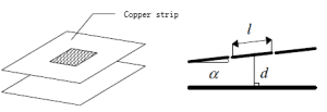
Then the capacitance value between the two electrodes can be expressed as:

Where w is the width of the copper strip electrode, l is the electrode length, d is the distance between the electrodes, ε0=8.854187817x10⁻¹²F/m, so that the measured value can be calculated according to the relative dielectric constant of the medium and the geometric size of the electrode Capacitance value. We know that the detection range of PCS0902 in standard mode is 0~48pF. The length of the copper strip usually needs to cover the height of the barrel. Therefore, we need to adjust the width w of the copper strip so that the capacitance value obtained in the full barrel state is slightly smaller than The highest range of PCS0902.
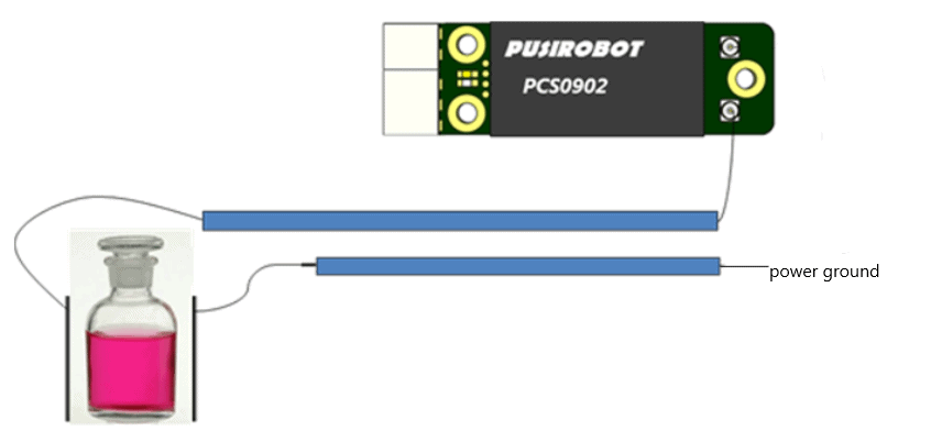
Next, let’s enter the actual test. The first is the test method and tools: PCS0902 capacitive liquid level detection module single-ended mode 1 is used for detection, the J4 interface cable core wire is connected to the outer copper plate of the container, and the other side of the container is connected to the power supply. Ground. Run the PUSICAN tool software of PUSIROBOT on the host computer for real-time waveform monitoring.
Detection diagram:
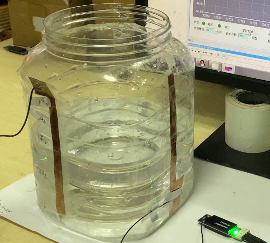
Experimental environment diagram:
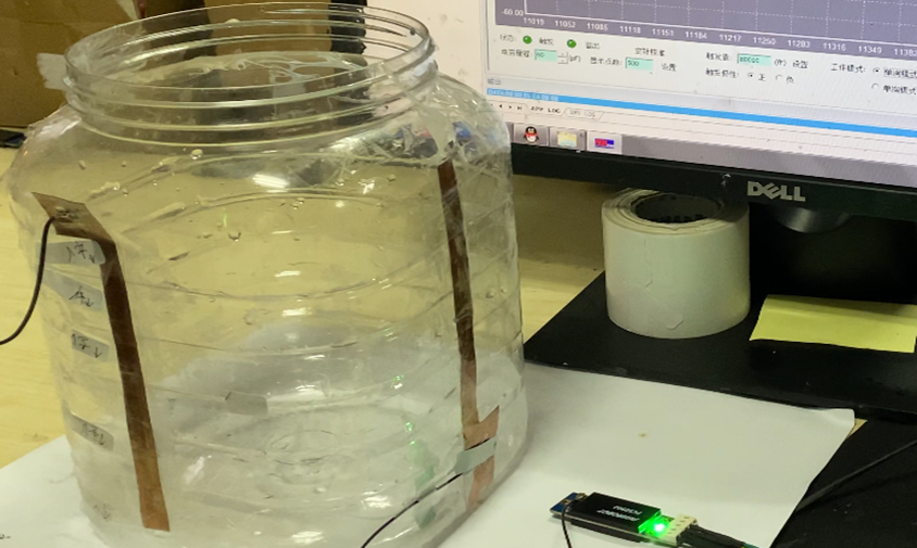
Test medium: pure water
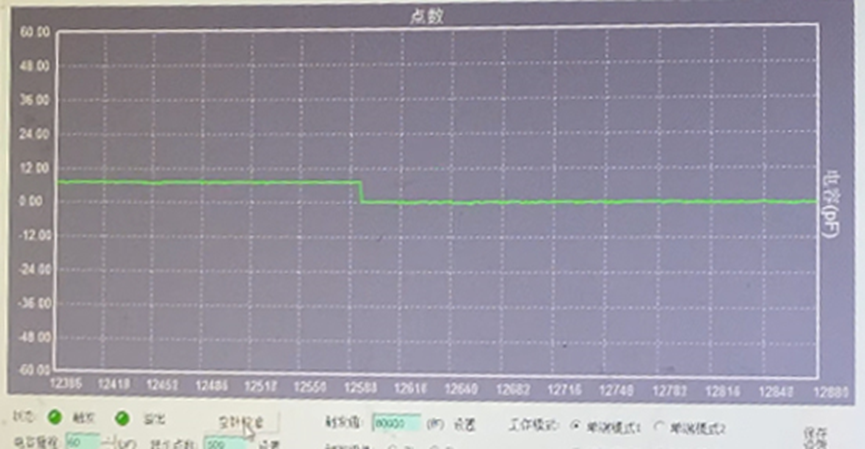
After the equipment is set up, the detection curve of the empty needle capacitance value after the first startup: almost no fluctuation, the basic capacitance value is about 8pF, not at the zero line.
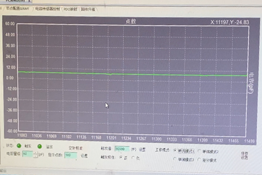
Click the capacitance value detection curve after the empty needle is calibrated: the capacitance value returns to the vicinity of the zero line without fluctuation.
The image shows that the waveform is stable, and then we perform liquid injection. The first injection: inject half a bucket of tap water. The situation after injection is as follows:
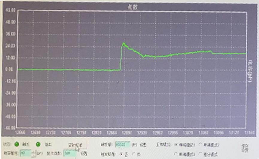
The image shows that the image fluctuates after filling half a bucket of tap water. This is because the large capacitance of the human body caused interference when filling the pot with the hand. It can be seen that the capacitance value is about 18pF after stabilization. The image after stabilization is shown in the figure below, and the waveform is stable:
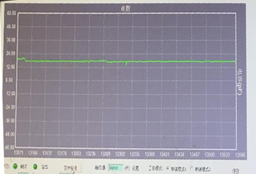
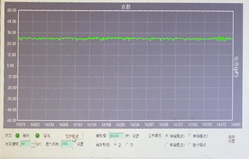
Next, we perform a second injection: inject tap water again until the bucket is full. The situation after injection is as follows:
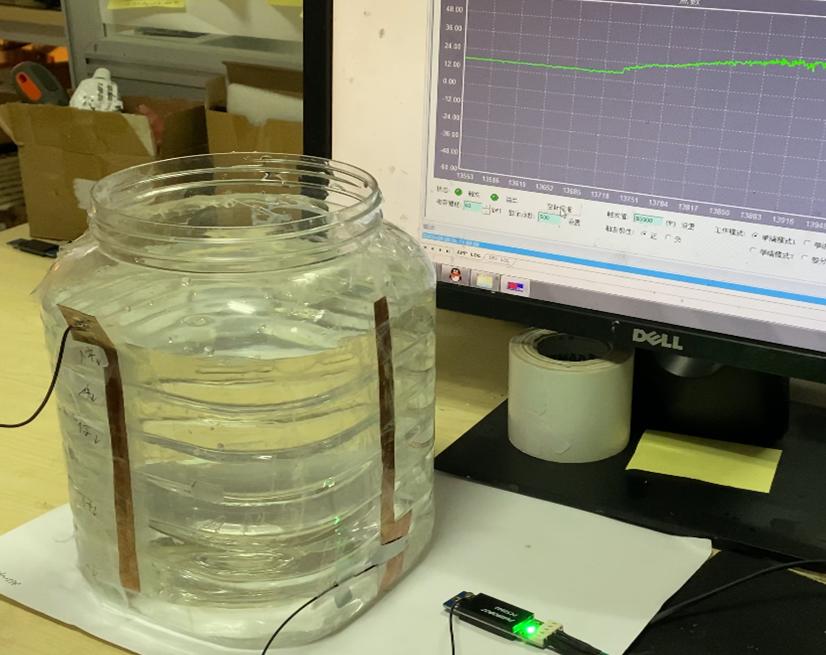
The image shows: When the water injection process is over, the fluctuation disappears, and the capacitance value is about 30pF after stabilization. The image after stabilization is shown in the figure below, and the waveform is stable:
According to the above experiment, in the case of empty bucket, half bucket, or full bucket, the capacitance value changes significantly. That is to say, we can use this non-contact test method to test the capacitance value of the container liquid at different positions, so as to know the position of the liquid in the container. In practical applications, if the capacitance value fluctuates due to the connection of the system's liquid path when the liquid is discharged to the waste water tank, it can be shielded by time-sharing reading through the bus; usually there will be no obvious fluctuations in the discharge process , You can use the trigger mode to set the trigger threshold to the capacitance value close to the full bucket in advance. Once the water level is reached, the PCS0902 will send an interrupt signal to the host computer.