- Welcome to Pulse Robot
- +86-23-63207381
- +8613677602178
- sales@pusirobot.com
The effect of the stepper motor micro stepping on the performance of the motion platform
The PUSIROBOT stepper motor microstepping drive circuit can not only improve the smoothness of the work platform, but also effectively improve the positioning accuracy of the work platform. The test shows that when the stepper motor 4 is subdivided, each step of the motor can be accurately positioned.
At present, the motion platform on the automation equipment uses a large number of synchronous belt transmission mechanisms, and the speed and position of its motion are controlled by a stepper motor. In order to enable users to use stepper motors correctly, we have analyzed and tested the relationship between stepper motor subdivision multiple and platform motion stability and positioning accuracy, and have drawn some valuable conclusions.
1. Stepper motor subdivision principle
The figure 1 is a schematic diagram of the working principle of a two-phase stepper motor. It has 2 windings A and B
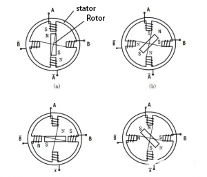
When a winding is energized, its stator pole generates a magnetic field, attracting the rotor to this pole. If the winding is under the control pulse, the energization direction sequence is as follows:
AA ® BB ®A A ® B B
These four states change over and over again, and the motor can rotate clockwise; each time the control pulse is applied, the power-on direction changes once, causing the motor to rotate one step, that is, 90 degrees. 4 pulses, the motor rotates once.
The principle of the microstepping drive is to change the angle of the synthesized magnetic field by changing the magnitude of the A and B phase currents, so that a step angle can be subdivided into multiple steps. When the A and B phase windings are energized at the same time, the rotor will stop in the middle of the A and B phase magnetic poles, as shown in Figure 1.b and d. If the power direction sequence is as follows:
AA ®AA + BB® BB® BB + A A ®A A ®A A + B B ® B B ®B B + AA
These 8 states change over and over again, the motor rotates clockwise; each step of the motor rotates at 45 degrees, and the 8 pulse motors make one revolution. Compared with the power-on sequence (1), its step angle is half smaller.
In order to ensure that the torque output by the motor is uniform, the magnitude of the coil current of the A and B phases should also be adjusted so that the resultant force generated by the A and B phases is the same at each position. Figure 2 shows the ratio of A and B phase coil currents when the motor is divided into four. Figure 3 shows the relationship between the current of the A and B phase coils and the rotation angle.
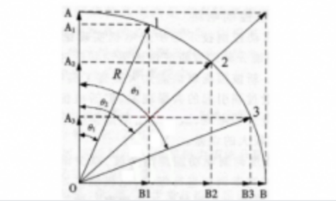
Figure 2 4 Distribution ratio of motor A and B coil currents at different angles during microstepping
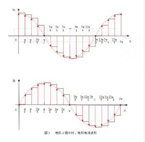
It can be seen from Figure 3 that the phase current of the stepper motor is distributed according to a sine function (as shown by the dotted line); the larger the microstepping, the closer the phase current is to the sine curve.
2. The relationship between stepper motor subdivision and motor smoothness Figures 4, 5 and 6 show the measured phase current waveforms of a two-phase stepper motor with 2 microstepping, 8 microstepping and 64 microstepping respectively. The step angle of the measured stepping motor is 1.8 degrees, that is, 200 steps per revolution without microstepping. During the test, the speed of the stepper motor is set to 2 r/s; when motor 2 is subdivided, the motor rotates 400 steps, and the period of each step is 1.25ms; when motor 8 is subdivided, the motor rotates every time It rotates 1600 steps, and the period of each step is 0.3125ms; when the motor is divided into 64, the motor rotates 12800 steps, and the period of each step is
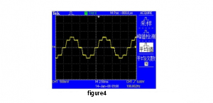
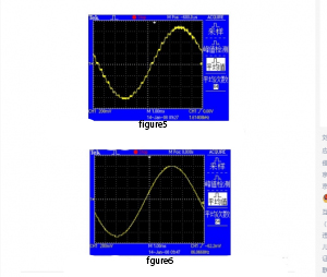
As can be seen from Figures 4, 5, and 6, when stepper motor 2 is subdivided, the current waveform steps are uniform, and the current ripple value is large, and the maximum value is 70.7% of the maximum current; when stepper motor 8 is subdivided, The current waveform has obvious steps, but the current ripple value is small, and its maximum value is 19.5% of the maximum current; when the stepper motor 64 is subdivided, the current waveform is smoother, and the current waveform is difficult to distinguish the number of steps, the maximum current The ripple value is only 2.45% of the maximum current.
According to the electromagnetic induction theorem, the output torque of a stepper motor is proportional to the current of the motor coil, and: T = KT × i where KT is the motor torque constant, which is related to the motor structure, material, coil length and other factors.
The formula is easy to understand: the higher the subdivision number of the stepper motor, the smoother the motor runs; the smaller the subdivision number of the stepper motor, the greater the vibration when the motor is running. Because when the number of microstepping is high, the current curve is smooth, so the output torque of the motor will fluctuate continuously and the motor will run smoothly; when the number of microstepping is small, the current ripple of the motor will be large, and the output torque ripple will be large, resulting in a larger motor. The vibration, the vibration and the noise and even the resonance noise of other parts.
2. The relationship between stepping motor microstepping multiple and positioning accuracy In order to quantitatively analyze the relationship between the microstepping number of the stepper motor and the positioning accuracy of the motion platform, we conducted multiple sets of tests on a motion platform driven by a synchronous belt.
The movement platform is driven by the integrated stepping motor of PUSIROBOT 57-76 CAN bus, the circumference of the synchronous belt wheel driving wheel is 100mm; the worktable is equipped with a grating ruler with a resolution of 0.001mm as a position detection device. The movement of the worktable is controlled by the spectrum motion control card, and the position signal of the grating ruler is collected by the spectrum counter card as data for analyzing the positioning accuracy of the motion platform.