- Welcome to Pulse Robot
- +86-23-63207381
- +8613677602178
- sales@pusirobot.com
Pneumatic liquid level sensor design scheme for medical applications
Liquid level detection is widely used in medical laboratory equipment and laboratory equipment. In order to improve reaction efficiency and reduce reagent consumption, it is necessary to add samples to respond quickly and accurately to the liquid level. This article will describe a design that uses an embedded signal processor and a mature MEMS air pressure sensor, as well as a dedicated low-drift and low-delay filter algorithm, to achieve the air pressure type high-precision fast detection function of the liquid level of the TIP head.
Overview
At present, the mainstream detection methods are capacitive and pneumatic. Generally speaking, the capacitive method has faster response speed and higher detection accuracy. For example, PCS0902 can perform microsecond level detection of reagents as low as tens of microliters. Response. But for reagents or ionic solutions with higher conductivity, the capacitive method requires strict isolation procedures to eliminate the influence of the back-end liquid path, so the structure and software requirements will be relatively high. This design uses embedded signals The processor and mature MEMS air pressure sensor, as well as a special low-drift and low-delay filter algorithm, realize the air pressure-type high-precision fast detection function of the liquid level of the TIP head.
Detection principle
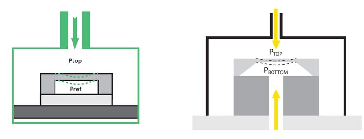
The air pressure sensor is the core device of this program. In order to improve sensitivity and stability, manufacturers generally use MEMS technology to manufacture, which can be divided into capacitive and resistive types. Usually four deformable resistors or capacitors are distributed on the force plane, and bridge circuits are used. Detect small pressure changes, and the detection accuracy can reach 0.005hPa, as shown in Figure 3-1 below. According to the different design of the reference pressure point, it can be divided into three types: gauge pressure, differential type and absolute type; according to different output interface types, it can be divided into digital type and analog type. Digital sensor integration is relatively simple, but usually at the expense of response speed, accuracy and flexibility, and because the sampling and quantification links are solidified in the chip, it is difficult to optimize the back-end according to the application scenario. This module selects analog differential air pressure sensor for program design.
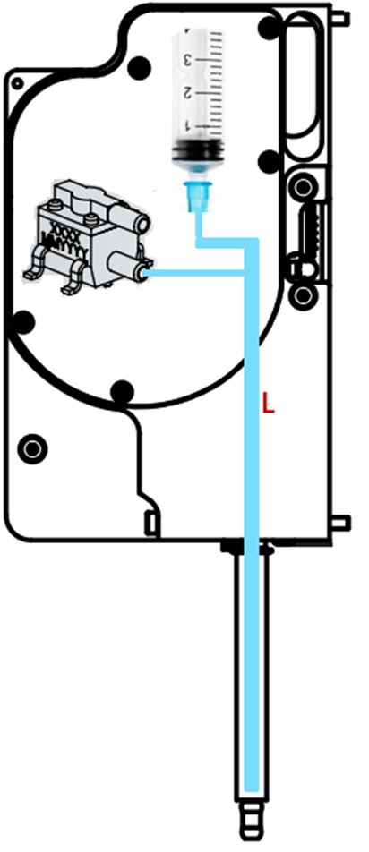
In pipetting applications, the pump, air pressure sensor, and pipette tip are arranged in a closed pipeline L, as shown in Figure 3-2 below. When the sample application arm descends, the TIP head contacts the liquid surface, causing a pressure change in the closed pipe L, so that the module can detect the liquid surface. When the sample application arm is drawing liquid samples, the closed pipe L maintains a specific negative pressure value. If a clot blocks the TIP head and the pressure value drops sharply, the sensor will be able to detect this abnormality. When the sample arm is spitting liquid, the closed pipe L maintains a specific positive pressure value. If a clot blocks the TIP head, the pressure value rises sharply. This abnormal change can also be detected by the module.
System outline design
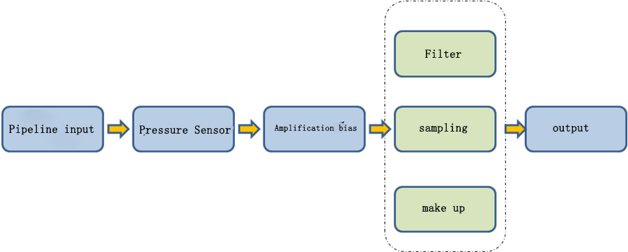
This module is mainly composed of air pressure sensor, bias interface circuit, and microprocessor, as shown in Figure 4-1. Among them, tasks such as sampling, filtering and compensation are completed in the microprocessor. The module interacts with the host computer through the interrupt signal and CAN bus, obtains parameter configuration and work mode control information, and outputs the result data and interrupt level.
3.1 Air pressure input
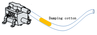
According to the requirements of the pipetting application, the differential air pressure input is selected as mentioned above, and one of them is connected to the pipe L shown in Figure 3-2 through a sealed pipe. Since the sensor is installed on the PCB, in order to facilitate the sealing connection, a sensor with a tapered interface can be selected. It should be noted that in order to enable the module to correctly detect the small pressure difference at different altitudes, the other reference pipeline should pass through the damping cotton and Atmospheric connection, as shown in Figure below, on the one hand, it filters out instantaneous high-frequency pressure interference, on the other hand, it can follow small changes in altitude (because high-precision sensors are very sensitive to changes in altitude), structural design needs to consider comprehensive considerations Leave space for piping.
3.2 Amplification bias
Since the air pressure sensor with differential analog output is essentially a resistance or capacitance bridge, the signal must be biased, coupled, amplified and other preprocessing before it can be sent to the sample holder. Taking the 26PC series as an example, when the power supply is 5V, the maximum output range is +2.4~+2.6V, and due to the existence of vibration, sound pressure disturbance and other factors, when the input pressure difference is 0, the output voltage will not be It is the +2.5V reference point, so before the signal is amplified and sampled, it must be preprocessed. The circuit is as follows
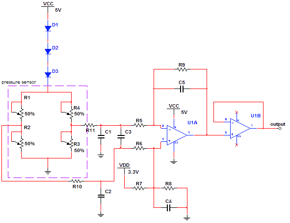
Among them, R1~R4 are the internal resistance and piezoelectric resistance of the sensor. The low-amplitude differential signal from the sensor is pre-filtered, then biased and amplified, and the output point is set at 1.65V, and then sent to S through the buffer /H, in order to adapt to the current mainstream 3.3V embedded processor input pins. D1~D3 provide simple temperature offset compensation at the power supply end, and a current source can also be used instead to achieve more accurate temperature offset compensation. Since the signal amplitude is as low as 1mV, high-precision (1‰) resistors with low temperature coefficients, and op-amp devices with low offset and high bandwidth are required.
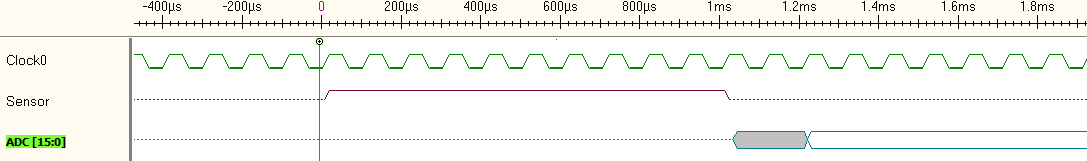
3.3 Signal sampling
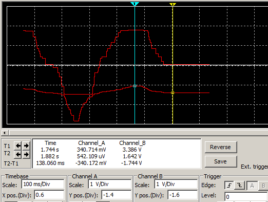
Still taking 26PC as an example, its response time is the maximum 1ms, and the average value is 500us. According to the sampling theorem, the lowest frequency of S/H should be 4khz. The front-end signal waveform of the circuit is shown in Figure 4-4. When the static operating point is At 1.65V, the 26PC01 outputs 0.5% psi increments within the measurement range, which is 83.5uV. According to the calculation of 200 times expansion, the gain bandwidth of OP needs to meet at least 800khz, and the input bias voltage should be less than 80uV, and the front-end differential mode sum The common mode filter frequency point also needs to be set as follows.
3.4 Filter
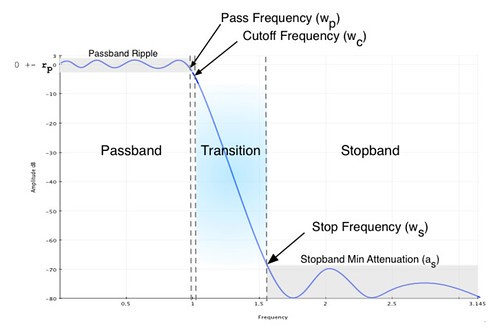
In addition to using hardware for common mode and differential mode filtering in the front-end circuit, the main signal processing uses software digital IIR filters. This is similar to PAS0700. First, according to the response characteristics of the sensor, design a Butterworth low-pass, as shown in Figure 4-5, according to the processor's MIPS and floating-point computing capabilities, comprehensively considering the order (N <= 8), filter out the pump motor High-frequency sound waves and other noise (Wc <= 3khz); Then, according to the acquired original sample data, do FFT analysis of the notch and low-frequency stop band in the middle and low frequency bands, filter out the power frequency, temperature drift, machine or sample arm vibration, etc. Noise range.
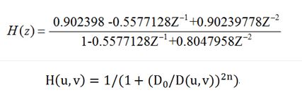
The notch filter used for the power frequency and its multipliers, the order of which will not exceed 3, is as follows: transfer function 1; handles high-pass with slow temperature drift, similar to the low-frequency filter of a microphone, such as transfer function 2; for specific vibrations For the noise spectrum, the corresponding bandpass order may be slightly larger.
Taking into account the CANOPEN communication protocol and other interrupt processing, the total filter calculation overhead should be limited to 150us/Cycle, which is slightly smaller than the PCS0902 filter, otherwise you need to use a higher MIPS processor.
3.5 make up
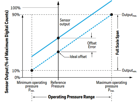
The MEMS device air pressure sensor has greater temperature sensitivity, because the temperature can easily cause the internal piezoelectric material to deform, and the wafer will also cause stress and deformation at the connection part due to temperature changes, which will cause the measurement results to shift. Time, different work locations may bring greater deviations. In addition, the installation of the workstation, airflow, vibration and other factors will also bring certain deviations. Usually these factors will not affect the range and sensitivity of the sensor, that is to say, its transfer function still follows the y = mx + b The form is shown in Figure 4-6 below, so corresponding compensation measures can be taken on the software.
The compensation process is divided into the following steps:
①First, when the pressure is given, the output voltage value of the sensor satisfies the following equation:
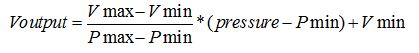
Among them, Pmax is the maximum working pressure, Pmin is the minimum working pressure, and Vmax and Vmin correspond to the output voltages in these two cases respectively.
②In the second step, after the MCU obtains the filtered voltage value, it amplifies the bias coefficient according to the aforementioned circuit and converts it to the sensor output voltage Voutput, and then calculates the pressure according to the above formula:
③In the third step, subtract the reference pressure value from the calculated pressure value (for example, the default current is 0) to get the compensated pressure value:
Calib_pressure = pressure – Ref_pressure
④ In the fourth step, in the subsequent operations, use the pressure value calculated after each measurement to subtract Calib_pressure to obtain the pressure value after calibration, until the next calibration update Calib_pressure.
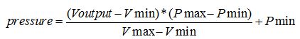
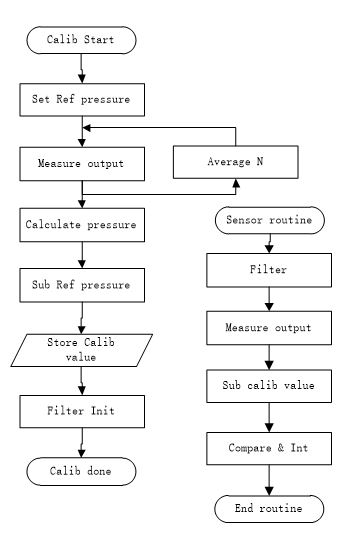
3.6、State machine and process
The main state machine of the embedded software, as well as the calibration and sensor routines are shown in the figure below. Among them, the filter routine takes up the most processing time, which involves a considerable amount of floating-point operations. If you choose a processor with a hardware FPU above 100Mhz according to PCS0902, the total time of a single process cycle can be controlled within 150us.
Main design index
The technical indicators of this solution module mainly include detection accuracy, linearity, response time, working range, overload range, temperature range, etc. Among them, detection accuracy and response time are the two most important indicators for pipetting applications, which are detailed below.
4.1 Detection accuracy
In some pipetting applications, due to the high cost of conductive carbon TIP heads, disposable insulated TIP heads are required. In this case, capacitive or inductive liquid level sensors may greatly reduce their sensitivity, so pneumatic liquid level sensors are required. The bit module can reach or be close to the detection accuracy of PCS0902, such as 20uL H2O. Taking this as an example, the relevant constraint conditions are calculated below.
Take 20uL commonly used disposable TIP as an example, its structure size is as follows:
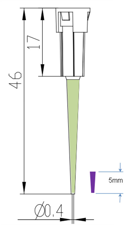
The total volume of the 29mm conical cavity is 20uL. Assuming that the maximum allowable insertion depth of the liquid surface is 5mm, the pressure increase in the tube is:
The accuracy of 26PC01 is +/-0.5% psi, which is about 34.5Pa, so in theory it should be possible to detect the liquid level, but it is already very close to the limit of the sensor. If the BM1383 sensor is selected, the accuracy range is 12~100Pa, and the DPS3130 is 6~100Pa, the consistency may become worse, and the domestically produced replacement SPRA001 of 26PC01, the accuracy can only reach +/-2%psi, in addition Some sensors can only pass through the air, such as SDP3x, which is not suitable for such scenarios. In fact, the 5mm TIP immersion depth is already very deep in small-volume pipetting.PCS0902 detects 10uL of liquid during the downward movement of the probe, and the immersion depth is only about 1mm. This shows that it is compatible with special capacitive liquids such as PCS0902 Compared with the position sensor, the air pressure type has a substantial bottleneck in the application of small-volume high-precision liquid level detection, and may be more used for supplementary purposes such as detecting clot clogging.
4.2Working area
Since the overload interval of the high-precision air pressure sensor is relatively small, it is necessary to calculate the working conditions at the maximum pipetting volume. Take the 1250uL large-capacity TIP header as an example, and its structure is as shown in the figure below

When the TIP head draws 1250uL of liquid at a flow rate of V, the pressure difference that the sensor bears is the largest.
Assuming that the extraction speed is 500uL/s, normalized according to 1mm3, there are:
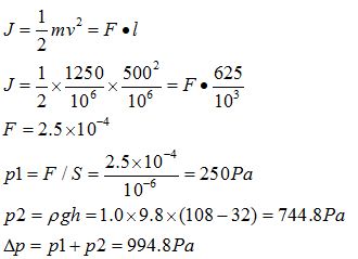
That is to say, under normal working conditions, 1250uL of H2O is pumped at a speed of 500uL/s, and the maximum pressure difference of the sensor port accounts for about 15% of the full scale of 26PC01, and the margin is quite sufficient.
Response time
The response time mainly depends on the sensor selection, 26PC series is 1ms; BM1383 is 6ms, plus I2C transmission time is about 80us; DPS3130 is as high as 27.6ms. Other time consumption is mainly the filter calculation time. 150us is reserved. The delay of the pre-filter circuit is less than 10us and can be ignored. Therefore, if the 26PC series is selected, the fastest response time that can be achieved is about 1.16ms, which is an order of magnitude higher than the 100us response time of PCS0902, which may cause firing pin failure in small-volume liquid level detection applications.
Electrical integration
Mainly describe the module's requirements and influence on power supply, EMC, PCBA, etc.
5.1 power supply
The core of this module scheme is essentially an effective combination of a precision analog signal processing circuit and a digital filter. According to the calculation of the aforementioned parameters, in order to obtain the desired accuracy and consistency, it is necessary to ensure that the uV-level useful signal of the front-end circuit is not submerged by various mV-level noise sources, and the power supply is one of the most important factors.
The 26PC series uses 2.5~16V voltage power supply. Due to the noise ripple requirements, it cannot be directly powered by DCDC. It needs to pass a low-noise LDO such as ADP7104, etc., so that the root mean square noise within the 3khz bandwidth is lower than 40uV RMS. Some LDOs The phase margin is low, so you should try to use fixed-point output instead of adjustable output devices, as shown in Figure 6-1 below:
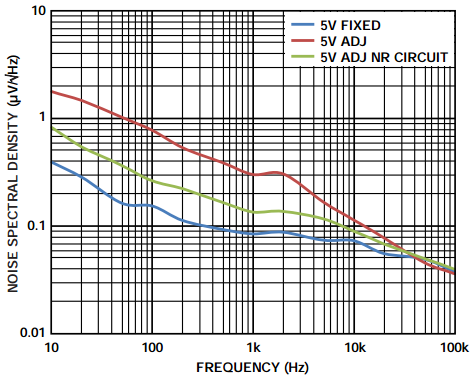
In addition, the PSRR also needs to reach about 60dB around 3khz. Generally, a low-noise LDO can achieve the desired effect under such a small current load. If the actual measurement still needs improvement, you can use pre- and post-filtering in the LDO current, as shown in Figure below:
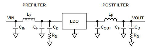
In addition, following the general rules, the capacitor used should be a Class1 ceramic capacitor with low ESR and a temperature coefficient of 0ppm/°C.
5.2 PCBA
The impact of PCB layout and routing on sensitive small signals is unquestionable, except for some basic rules, such as the division of digital and analog signals and the cutting of ground plane loops, the differential wiring between the input terminal and the OP, the location of components and the signal Layering, etc., also need to pay extra attention to the influence of parasitic inductance and capacitance on the amplifier bias circuit to ensure that the circuit works within the design parameter range. In addition, due to the special nature of the air pressure sensor, the following aspects need to be paid special attention to in the layout and SMT process:
No components can be placed in the PCB area on the back of the sensor;
The mounting holes and stress concentration points should be far away from the sensor;
The SMT picking mechanism should select the pipe interface position when clamping the device;
Do not use vacuum nozzles, make sure that the two pipeline ports of the sensor are always under standard atmospheric pressure;
When using solder paste or positioning glue, avoid blocking the air holes of the sensor;
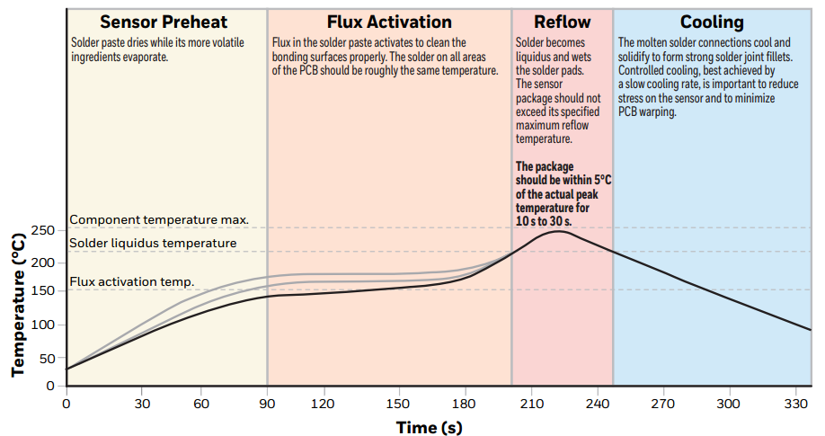
Ultrasonic cleaning cannot be used after PCBA is completed; Minimize all vibration and stress during the process;
Strictly follow the temperature curve of the device during reflow soldering, as shown in the figure below
Summary
The above focuses on the design of the pneumatic liquid level sensor. The design points related to key indicators such as design accuracy and response time are described in detail, and the points to be considered are discussed from various aspects such as structure, circuit, signal processing, workflow, and manufacturing. The key point, I hope to help relevant instrument engineers sort out their ideas, avoid detours, and realize product solutions faster.