- Welcome to Pulse Robot
- +86-23-63207381
- +8613677602178
- sales@pusirobot.com
Wiring requirements of stepper motor controller
Wiring requirements of stepper motor controller
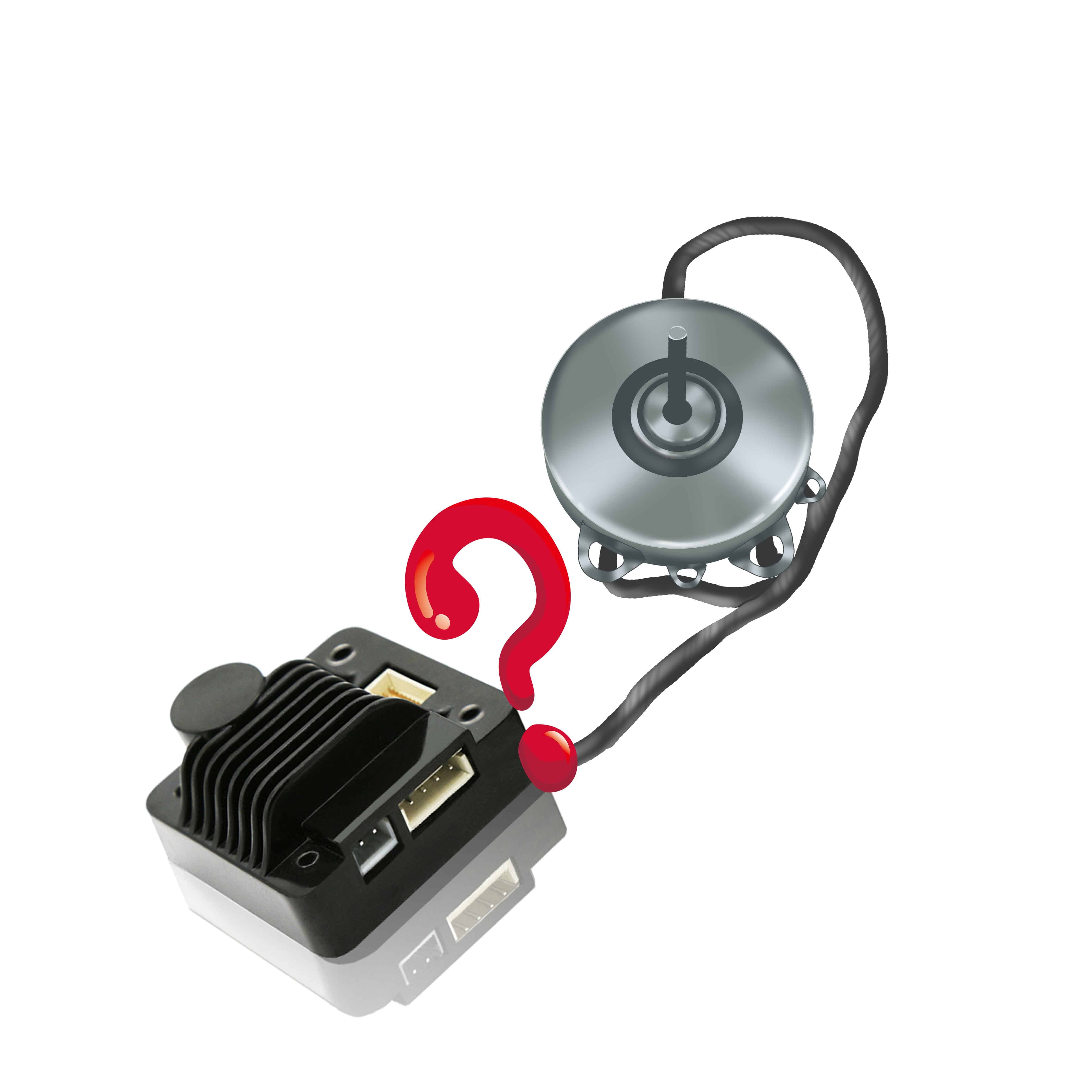
Many friends who are new to stepper motors are not very clear about the wiring requirements of stepper motors, so there may be some irregular wiring or operations, which may easily cause the controller to malfunction or cause permanent damage to the controller. This summarizes the wiring requirements of the following stepper motor controllers:
- In order to prevent the controller from being interfered, it is recommended to use twisted-pair shielded cables and connect the shielding layer to the ground wire. In the same machine, it is only allowed to be grounded at the same point. If it is not a real grounding wire, there may be serious interference. At this time, it is recommended not to connect the shielding layer.
- The pulse direction signal line and the motor line are not allowed to be connected side by side, preferably at least 10cm apart, otherwise the electromagnetic interference of the motor will easily cause errors in the pulse direction signal and cause malfunctions such as inaccurate positioning of the stepper motor and unstable system operation.
- If multiple stepper motor controllers share one power supply, they should be connected in parallel, and series connection is not allowed.
- Do not hot-swap the power terminals and signal wire terminals of the stepper motor controller when the power is on, because a large current still flows through the coil when the stepper motor is stopped.Hot-swappable terminals will cause a huge momentary induced electromotive force which will permanently damage the controller
- Do not add tin to the terminal of the motor lead, otherwise the contact resistance may increase and the terminal may be damaged due to overheating.

