- Welcome to Pulse Robot
- +86-23-63207381
- +8613677602178
- sales@pusirobot.com
The PMC005 multi-axis controller of PUSIROBOT
The application and problem analysis of PMC005 in IVD industry
1. The application in the IVD industry?
At present, the most widely used control mode in the IVD industry is the control system composed of servo stepping, and the host computer (MCU, PLC, computer) sends control commands to the driver. The driver amplifies the pulse signal to drive the motor to run to achieve the purpose of precise positioning. This type of system is currently used in many medical applications. The most typical devices are automatic biochemical analyzers, micro-pumps, surgical robots, and gene sequencers.
The upstream of in vitro diagnostic instruments are mainly molds, mechanical parts, electronic and optical devices. Non-standard products such as molds, machined parts and circuit boards required for instrument production are processed through outsourcing. Key components such as micro-motors and plunger pumps are mainly imported. On the whole, the upstream of the instrument has basically achieved localization. However, the core components and high-precision technologies of immunological and molecular diagnostic instruments are still monopolized by foreign patents.
At present, the multi-axis synchronous controllers on the market, such as TRINAMIC, Toshiba and other manufacturers, have the disadvantages of being too large in size and high in price.When the available space of the equipment is small or the development cost is limited, this kind of multi-axis controller is not suitable.
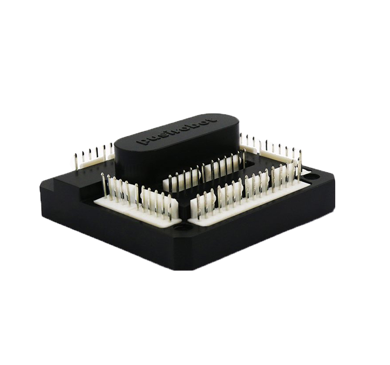
PMC005B3 is a multi-functional high-integration product independently developed by Pusi, which integrates multi-axis stepper parallel control, two-axis DC brush control and solenoid valve control.
Its small size, only 48.93mm*57.15mm, can be widely used in small and medium volume multi-axis motion control equipment. Secondly, using the DT protocol, the secondary development is simple, and the software engineer can immediately carry out development control.
Finally, it can match multi-axis motors with rated currents of 2.5A and below, and is suitable for medium and low torque equipment environments. At the same time, compared with the single-axis controller, the PMC005B3 has a great improvement in space and cost of use.
The high precision, high running stability and high response speed of the multi-axis controller, together with the PCS0902 liquid level detection module of PUSIROBOT, can be widely used in the medical equipment industry, assisting China's intelligent manufacturing, and helping the "localization" process of the medical equipment industry.
2. PMC005 Questions and Answers
Q: What is the main difference between the power connectors J1 and J2? In which scenarios do you need separate power supplies? Is the dual power interface design of J1 and J2 to consider that one of the interfaces supplies power to the driver board, and the other interface is used as a bridge to supply power to the motor through the driver board, so as to avoid interference to the driver board when the motor is working?
Answer: (1) There is no difference between J1 and J2, they are both power ports and are common; when two power ports are set for the customer to use a 57 motor, the input current exceeds the maximum rated current value (8.25A) of the power port, which causes Port burned out. (2) It cannot be used as a bridge to supply power to the motor for the same reasons as above.
Q: The following command, please explain "write 0 value to enter forward speed mode"? That is, if a value of 0 is written, what action or movement will the motor do? What will be the impact? Will it stop when the limit is reached? If it is in reverse speed mode, does it stop at the 0 o'clock position?
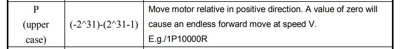
Answer: (1) When the limit is not enabled: if the stroke is long enough, the motor will continue to run in the positive direction without termination unless the customer issues a stop command (T command); if the stroke is limited, the motor will always run in the positive direction without termination Running, even if it encounters the end of the stroke, the motor will not stop unless the customer issues a stop command (T command);
(2) When the direction limit is enabled: the motor will always run in the positive direction without termination, unless the customer sends a stop command (T command), or triggers the direction limit switch (upper limit), the motor will stop running ;
(3) The speed mode of the D command is basically the same as that of the P command, except that the limit switch is the lower limit switch.
Q: The maximum communication rate of the 485 bus scheme is 57600; what is the rate of the CAN bus? Can you provide more information on the CAN bus version.
Answer: The rate supported by the CAN bus is: 9600~115200
Q: Please explain in detail the meaning of the following commands after they are executed, and in which scenarios are they used? Can you give an example?
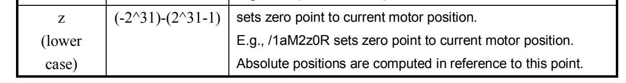
Answer: The z command is to set the current absolute position of the motor, and the command can only be sent to set the position value when the motor is stopped;
eg./1z1000R, set the position where the motor stops as the absolute position 1000. When the absolute position command A is used subsequently, assuming that "/1A60000R" is sent, the motor will run to the absolute position 60000. When the relative position command P or D is used subsequently, this data may change.
Q: Please give the analysis of the following driver board's return message to the following command.For example, when obtaining the current position of the 4-way motor, how to extract the current position of each motor from the content of the message returned by the driver board? Does the current position refer to the absolute position relative to 0 point? Is it the current position in pulse number?

Answer: The ?aA command reports the position of all four motors, the position value is the absolute position, and the response data is decimal. For example /1?aA Example response (axis 1 to 4 in order): 102000, 35000, 35000, 5000 No Error ?aV Reports the maximum speed set for all four motors and the response data is in decimal. For example, /1?aV Example responses (axis 1 to 4 in order): 568, 568, 568, 568No Error