- Welcome to Pulse Robot
- +86-23-63207381
- +8613677602178
- sales@pusirobot.com
Summary of common problems of capacitive liquid level detection module
As an efficient and low-cost detection method, capacitive liquid level detection is widely used in laboratory equipment. In the previous series of articles, we introduced several different liquid level detection solutions and their application scenarios, PCS0902, a basic device + algorithm liquid level module, to get rid of the excessive dependence on imported special chips and improve the safety of the supply chain. Sex and stability.
Q1: What kind of needle should be selected?
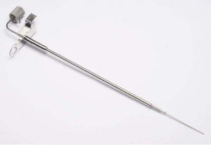
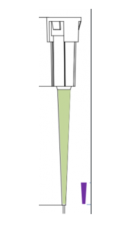
A1: It is recommended to use double-layer reagent needles with stable interlayer capacitance and good consistency, such as the double-layer needle of Ito Manufacturing Co., as shown in Figure 1. Insufficient grinding finish of the inner layer, or uneven insulation between layers, will cause the capacitance measurement value to drift randomly. When the reagent needle is hovering after a sample addition, this drift phenomenon can be observed by real-time monitoring of the waveform by the PUSICAN software To. In detection scenarios where accuracy requirements are not very high, single-layer steel needles can also be used, but in this case, special attention should be paid to the rack installation described in Q2.
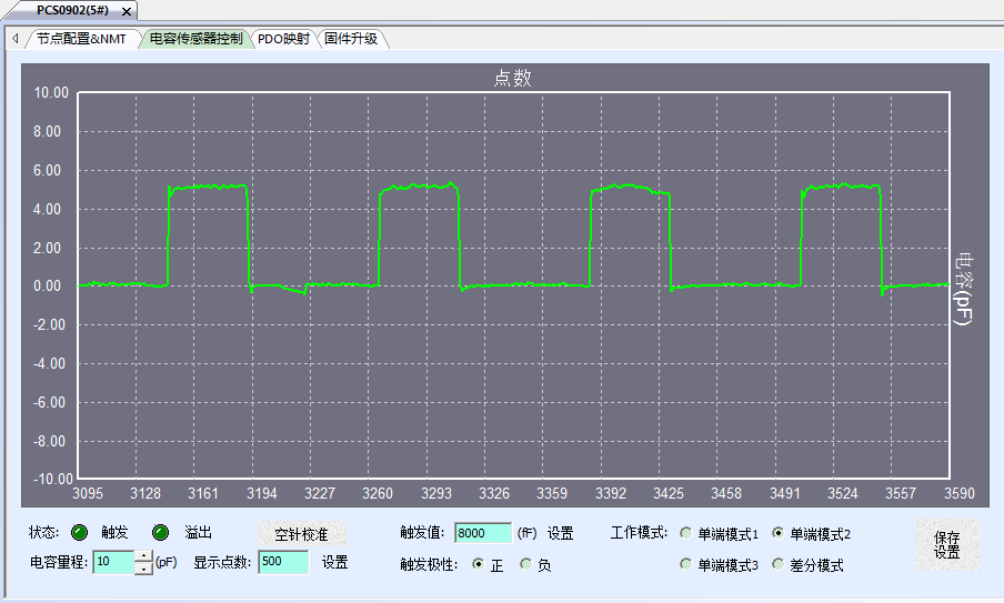
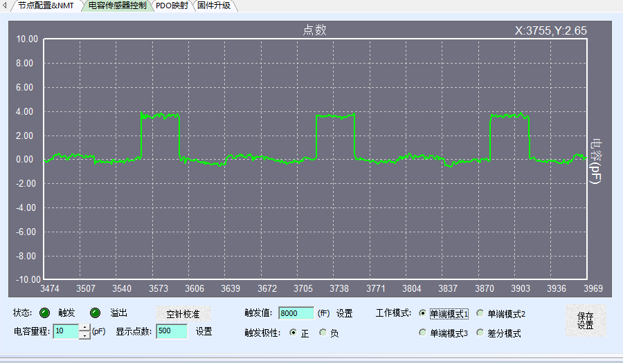
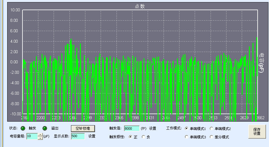
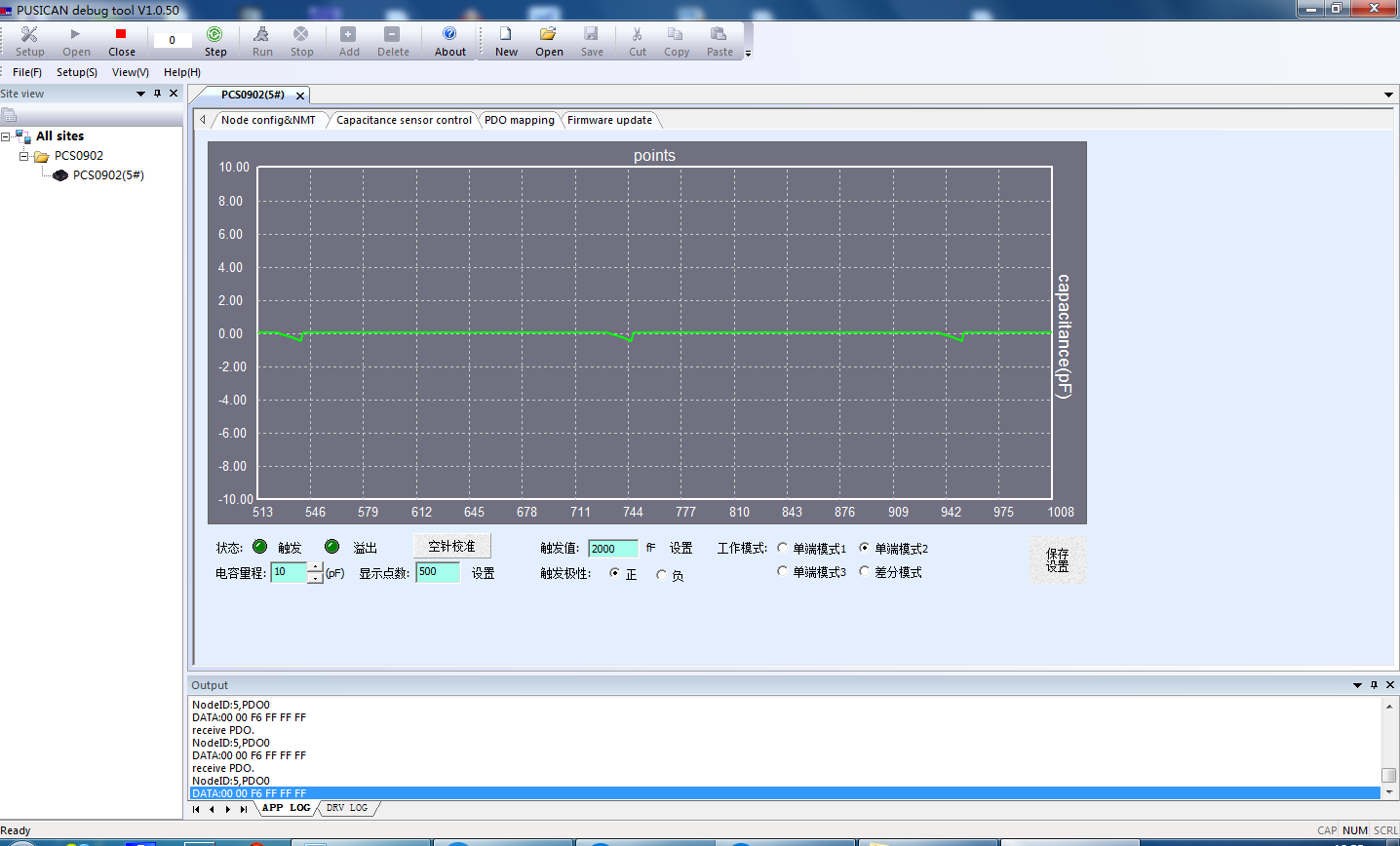
The quality of the reagent needle can be easily judged by the PUSICAN tool. First, disconnect the coaxial cable and the reagent needle, and directly use the core wire of the coaxial cable to contact the liquid surface. We will get the following figure 2 left from PUSICAN When the needle is hovering, the degree of waveform drift can be observed by observing the waveform of the needle; then connect the reagent to contact the liquid surface, and you may get a waveform similar to the right of Figure 2 below. Some poor-quality needles have serious waveform distortion; when the needle is hovering, you can observe the degree of waveform drift to judge the stability of the medium between the double-layer needles.
Q2: What is the influence of the frame structure and installation method on liquid level detection?
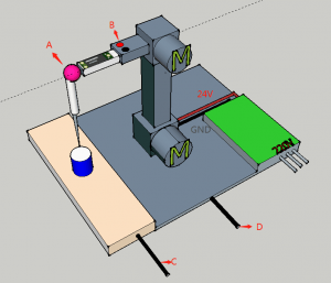
A2: Due to the distributed capacitance of the rack components, as well as the interference caused by the motors, solenoid valves, wiring, etc. installed on the rack, many engineers are usually confused by the messy data waveform when they connect the capacitor module for the first time. This also reflects the importance of the rack structure and installation method from the side, which requires coordination between the electronic engineer and the structural engineer in the design phase. A typical frame structure is shown below. In order to achieve the best detection effect, first, the connection A between the sample arm and the reagent needle should be made of a material with good insulation and a relatively stable dielectric constant, such as polyimide , And POM is relatively poor; secondly, in order to reduce the interference of the motor winding on the axis of the sample arm, both the sample arm B and the frame D should be connected to the 24V GND. If the 5V power supply of the PCS0902 is isolated from the 24V, the most Connect the bottom plate C of the test tube rack to the 5V GND.
Q3: Is it possible to use TIP header?
A3: Generally speaking, the disposable common TIP head is an insulating material, which cannot form an electrode with the core wire of the PCS0902 coaxial cable, so it cannot be used. However, conductive TIP heads, such as carbon TIP heads, can be used.
Q4: What are the precautions for the wiring of the sample needle?
A4: For double-layer pins, the inner layer of metal is connected to the PCS0902 coaxial cable core wire, and the outer layer of metal is connected to the PCS0902 coaxial cable shielding layer. Note that the outer layer of metal cannot be connected to GND; for single-layer pins, only the coaxial cable needs to be connected the core wire is fine. No matter what kind of sample needle is used, it is necessary to ensure that the coaxial shielded wire is connected to the connection of the sample needle as much as possible.
Q5: What are the special requirements for the power supply of the liquid level detection module?
A5: Generally, it is recommended to use the MCU system board VDC 5V power supply (ripple ≤20mV) on the instrument. If it can be isolated from the 24V used by the motor, better results will be achieved. Regardless of the power supply scheme, it is recommended to adopt Q2. The grounding method. The problem of the power supply can be easily identified by using the PUSICAN tool after unplugging the coaxial cable. Sometimes when the engineer uses the switching power supply to test, due to grounding, even if the probe or fluid circuit is not connected, it may be in the PUSICAN A very chaotic waveform is seen on the left, as shown on the left. At this time, once you switch to a pure power source (such as a battery), you will immediately see a flat contrast waveform, as shown on the right.
Q6: How to reduce the influence of the back-end liquid circuit on detection?
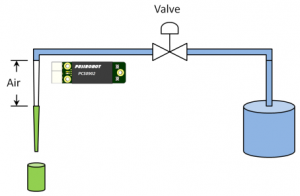
A6: When the inner wall of the sample needle is connected with the system water or cleaning fluid at the back end, it becomes very difficult to detect the small liquid in the test tube, which is equivalent to finding a small increment in a huge base fluctuation. Especially when there is conductive ionic liquid in the back-end pipeline, it is prone to saturation. The solution is usually to inhale an air column between the sample needle and the rear fluid path as isolation. For the conductive ion cleaning solution, it is best to install an isolation valve in the pipeline close to the sample needle, as shown in Figure 1, without an air column. The waveform monitored by PUSICAN during isolation is rather chaotic, and it is easy to see the overflow situation, as shown in Figure 2.
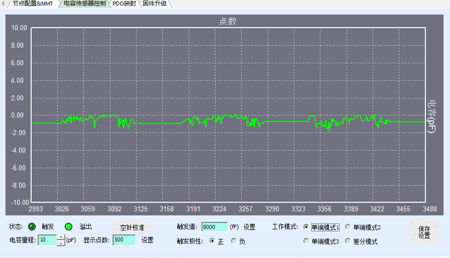
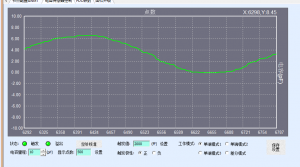
Q7: What is the reason for the sine wave type interference observed on PUSICAN?
A7: This kind of problem usually occurs when the back-end fluid circuit is connected and the power device on the instrument is turned on. The waveform observed by the PUSICAN software is as shown in the figure below. This type of interference waveform is generally caused by the following three reasons: One is the back-end conductive solution (Ionic liquid) is coupled with the power equipment, the other is that the non-conductive solution (such as pure water) is polarized by the high-power water pump and other equipment, and the other is the introduction of the power terminal. The first two solutions are to improve the grounding of the power equipment, especially the good grounding of the casing and the pipe connection; the second is to enhance the material insulation between the power equipment and the liquid circuit, and it is also necessary to increase the air according to the method of Q6. The column and isolation valve are blocked. The third solution can refer to Q5.
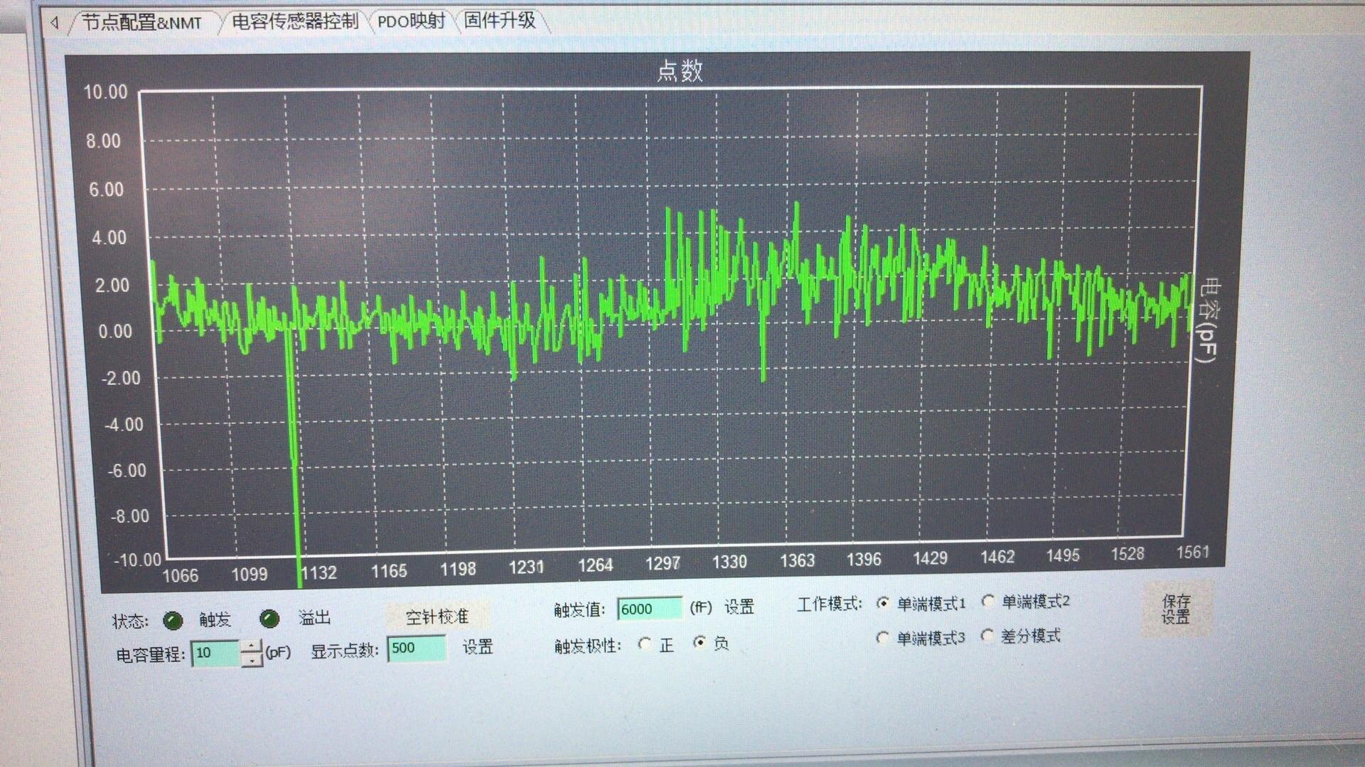
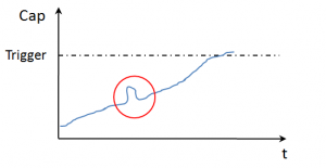
Q8: How to detect a slight abrupt change in a slow but large capacitance change?
A8: Some manufacturers' instruments will encounter this situation during long-term use. Even if the sample arm does not move, the observed capacitance waveform still rises or falls slowly, so that the amplitude exceeds the set detection threshold, causing the liquid level Detect misjudgment, as shown in the figure below. The solution is to use the sliding window mode of PCS0902, which can achieve reliable detection of small changes in the red circle in the figure through reasonable parameter settings.
Q9: What is the smallest amount of capacitance change that can be detected?
A9: Using the sliding window mode, PCS0902 can stably detect capacitance changes as low as 300fF. In the actual operation of the instrument, the corresponding minimum liquid volume is related to many factors such as the dielectric constant of the solution, the distributed capacitance of the rack and the test tube, and the interference of the liquid path.
Q10: The existing equipment has a source of interference that cannot be eliminated. How to improve the liquid level detection without changing the equipment?
A10: Some mass-produced equipment has been plagued by such problems. The equipment cannot be modified, but the inherent interference makes the false alarm rate of liquid level detection unable to improve. After-sales personnel have a headache for this. Thanks to the implementation of PCS0902's basic device + algorithm, we can use software to eliminate such problems. First, use the PUSICAN tool to capture the original data of PCS0902 in real time, and then analyze the original data, adjust the filter parameters in the algorithm, and eliminate specific interference sources in a targeted manner. The whole process does not involve the hardware or software on the customer's instrument. change.