- Welcome to Pulse Robot
- +86-23-63207381
- +8613677602178
- sales@pusirobot.com
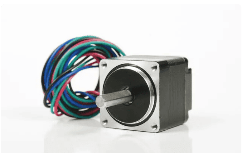
How to drive stepper motor
Stepper motors require some external electrical components to operate, which typically include a power supply, a logic sequencer, a switching part, and a clock pulse source that determines the step rate. Many commercially available drives have integrated these parts into a complete package(PUSIROBOT integrated stepper motors). Some basic drives have only the final power supply stage and no controller electronics that produce the proper step sequence.
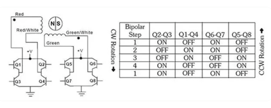
Bipolar drive
This is a very popular drive for two-phase bipolar motors with four wires. In a complete driver/controller, the electronics alternately reverse the current in each phase. The two-phase stepping sequence in the described adopts a "bipolar coil winding". Each stage consists of a single winding. By reversing the current in the windings, the electromagnetic polarity is reversed. The electrical schematic and step sequence in the figure below further illustrate the output stage of a typical two-phase bipolar drive. As shown in the diagram, the switching simply reverses the current flowing through the windings, thus changing the polarity of the phase.
Unipolar drive
A unipolar winding consists of two windings on one magnetic pole that are connected in such a way that when one winding is energized, a north magnetic pole is produced, and when the other winding is energized, a south magnetic pole is generated. This is known as a unipolar winding because the electrodity from the drive to the coil, i.e., the flow of current, is never reversed.
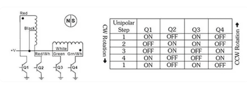
This drive requires a motor with a center tap in each phase (6 wires), and the driver does not need to reverse the current in each phase, but only needs to switch the current from one coil in each phase to another coil (as shown in the figure above). The windings are such that this switching reverses the magnetic field inside the motor. This option makes the drive simpler, but uses only half of the copper windings at all times. This results in approximately 30% less available torque for the rotating motor or force for the linear actuator than an equivalent bipolar motor, and the torque reduction is due to the energized coil utilizing only half the copper compared to the bipolar coil.
L/R drives
This type of driver is also known as a constant voltage driver. Many of these drivers can be configured to run bipolar or unipolar stepper motors. L/R represents the electrical relationship between inductance (L) and resistance (R). The relationship between the motor coil impedance and the step rate is determined by these parameters. The L/R driver should "match" the power supply output voltage to the rated voltage of the motor coil for continuous operation. Most published motor performance curves are based on the full range of voltage ratings applied on the motor leads. The power supply output voltage level must be set high enough to account for the power drop within the drive circuit for optimal continuous operation.
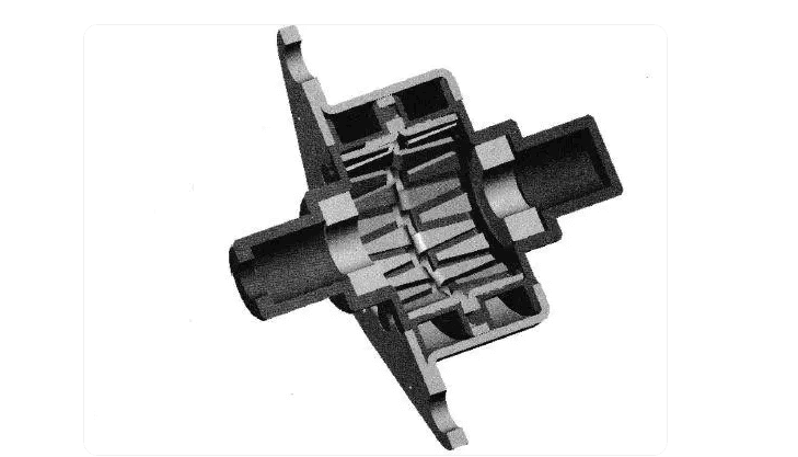
Other step corners
In order to obtain a smaller step angle, more poles are required on both the rotor and the stator, and the number of pole pairs required on the rotor is the same as the number of pole pairs on the stator. The rotor of a 7.5° motor has 12 pole pairs, each plate has 12 teeth. Each coil has two plates, and each motor has two coils, therefore, the 7.5° motor has 48 poles per step, and the following figure is a cross-sectional view of the 4 plates of a 7.5° motor. Of course, multiple steps can be combined to provide greater movement. For example, six steps of a 7.5° stepper motor can provide 45° of motion.
Micro stepper drivers
Many bipolar drivers offer a feature called microstepping, which electronically divides a complete step into smaller steps. For example, if a linear actuator has a step size of 0.001 inches, this can be driven to have 10 microsteps per step. In this case, one microstep is usually 0.0001 inches. The micro-stepping method effectively reduces the step increment of the motor. However, the accuracy of each microstep has a large percentage of error compared to the accuracy of the full step. As in the case of full step, the incremental error of microstepping is not cumulative.
Conclusion
The life of a stepper motor represents the number of cycles that can move and maintain stepper accuracy under a specified load, i.e., the fraction of operation, and the fatigue and life of the motor is determined by each customer's unique application. With the right application, running a stepper motor at its rated voltage provides up to 20 million cycles, providing up to 25,000 hours of service Running the motor at twice the rated voltage on an L/R drive, the motor is "on" approximately 25% of the time, and the motor produces 60% more output than at the rated voltage. Note that the duty cycle is independent of the load placed on the motor.