- Welcome to Pulse Robot
- +86-23-63207381
- +8613677602178
- sales@pusirobot.com
Capacitive level sensor controller PCS09xxP
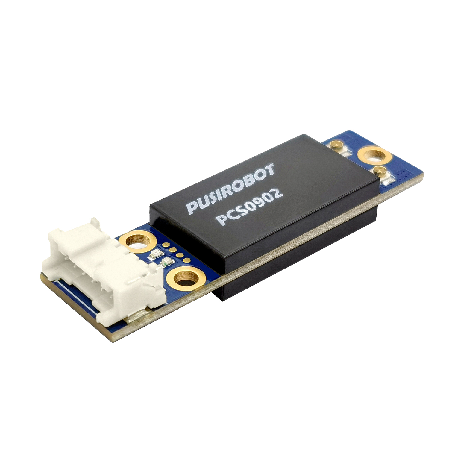
PCS09xxP
√ 2 capacitive sensor detection channels
√ the edge of digital level output can be configured
√ LED result indication
√ capactance detection range:0~2.5nf
√ accuracy of the capacitive :10fF
√ microsecond ultrafast response speed
√ using active shielding technology to improve dectection reliability
√ adaptive low frequency excitation circuit for ultra-low EMI radiation
Description
PCS09xxP is a programmable capacitive level sensor controller for liquid handling. The series controllers can detect capacitance which changes below 1pf, and can convert the test results into IO level output and intuitive LED indication. PCS09xx controller provides a simple and convenient set of control commands, which can be connected to the control host through CAN bus (or RS485 or RS232) and directly read the measured values. It is suitable for various medical, environmental protection, reagent level detection for laboratory instruments, container level detection and other application scenarios.
Technical data
General
|
Description
|
|
| Host |
PC PLC MCU
|
| Development environment |
VC C# Labview VB Linux Python
|
| Supply voltage |
DC9-24V
|
| Output trigger |
Digital level
|
| Capacitance detection accuracy |
10fF
|
| Capacitance detection range |
0-2.5nf
|
| Response speed |
Few microsecond
|
| Detection channel |
2
|
| Temperature range |
-20℃~80℃
|
| Durability |
Over 20,000 hours
|
Interface definition
| Interface |
Description
|
| J1 |
VCC: Dc power supply,9-24V GND:Ground |
| J2 |
CANH:CAN Bus high line
CANL:CAN Bus low line TR:5V Trigger signal output, can be configured high and low level trigger |
| J3 | Capacitance channel 2 interface |
| J4 |
Capacitance channel 1 interface
|
Communication
|
Description
|
|
| Protocol |
CANopen DS301/DS402
|
| Baud rate |
5K-1Mbps
|
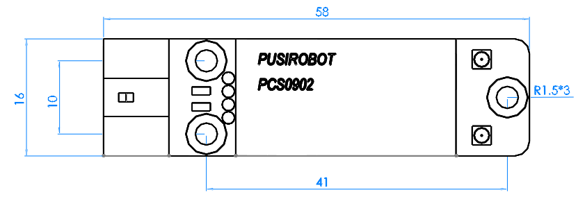
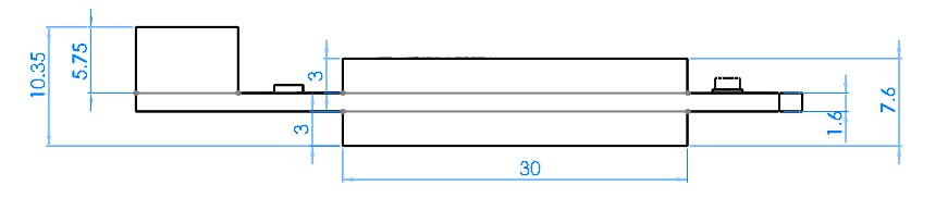
Dimensions
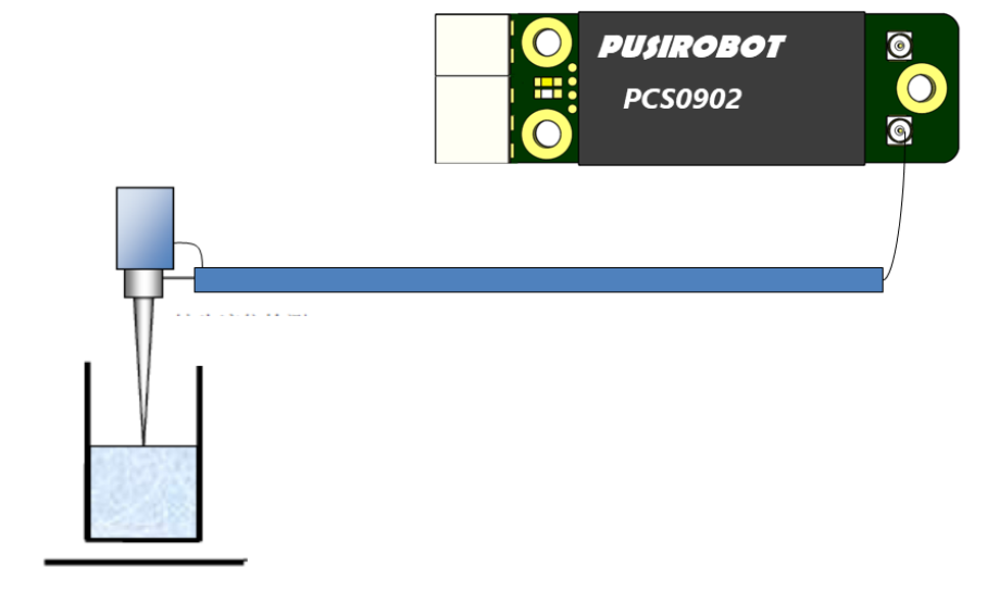
Typical application pattern wiring diagram
| Model |
Description
|
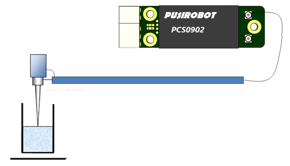
| Single-end mode 1 |
This mode selects the detection channel 1 work
|
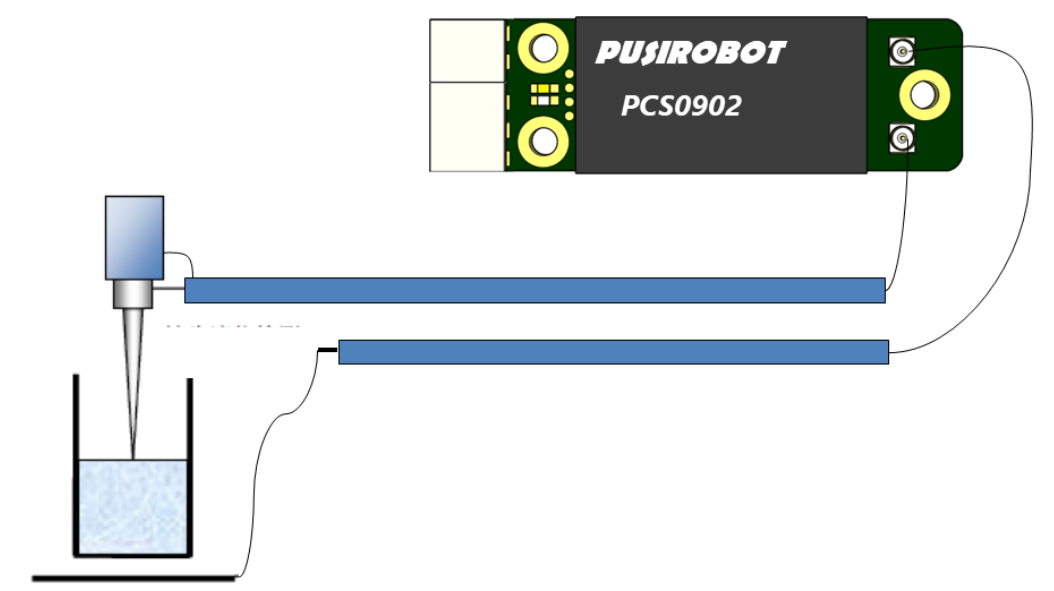
| Single-end mode 2 |
This mode selects the detection channel 2 work
 |
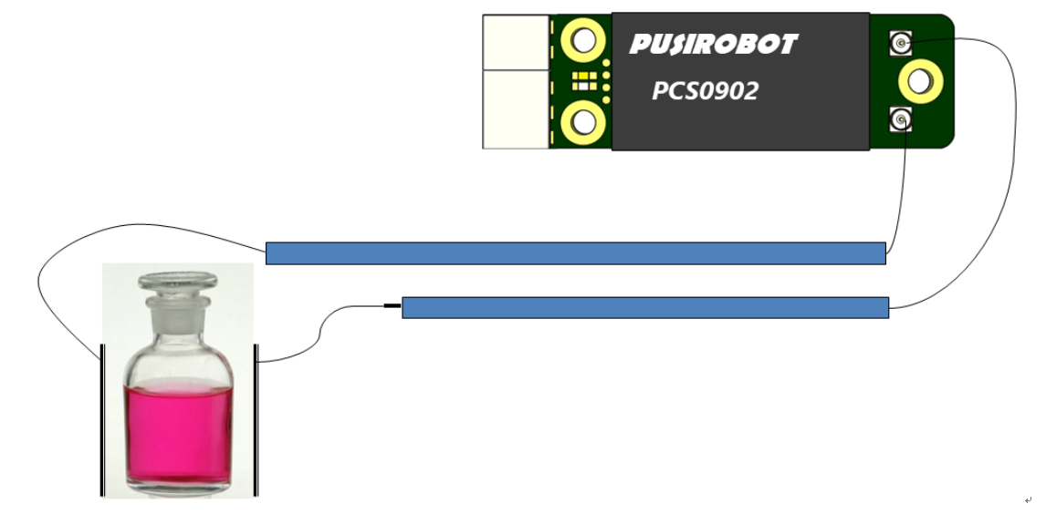
| Single-end mode 3 |
It is suitable for the reagent bottle or the liquid to be tested
|
| The differential mode |
This mode is non-contact measurement mode when the coupling capacitance of the equipment frame is very large
 |
Download
| CAD |
.DWG
|
| 3D file |
.STP
|
| The user manual | |
| Debug software | |
| Development of the document | |
| Certificate |
Functional features
| Function |
Description
|
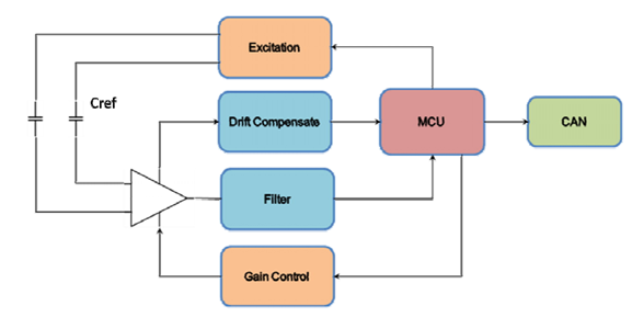
| Capacitance calibration |
Digital signal processing technology is used to control the measurement loop, which can improve the system reference capacitance detection significantly
|
| Optimize the algorithm to ensure the linearity of measurement |
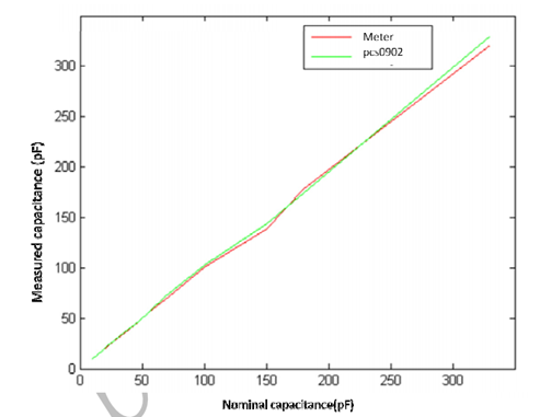 |
| Visual debugging interface |
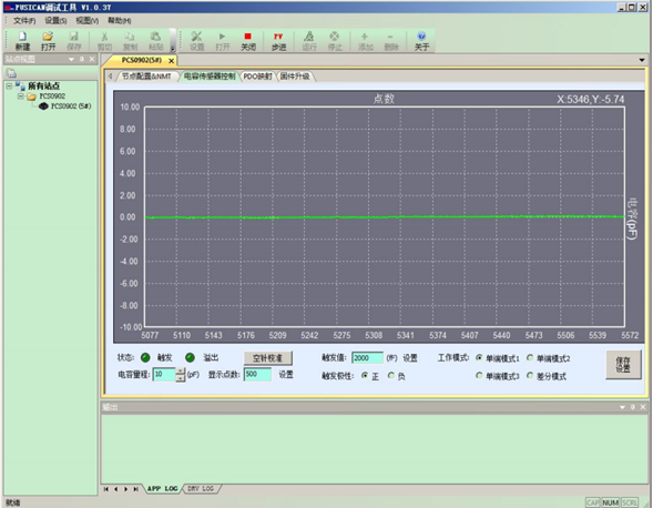
|