- Welcome to Pulse Robot
- +86-23-63207381
- +8613677602178
- sales@pusirobot.com
Micro pulse stepper motor driver PMD006
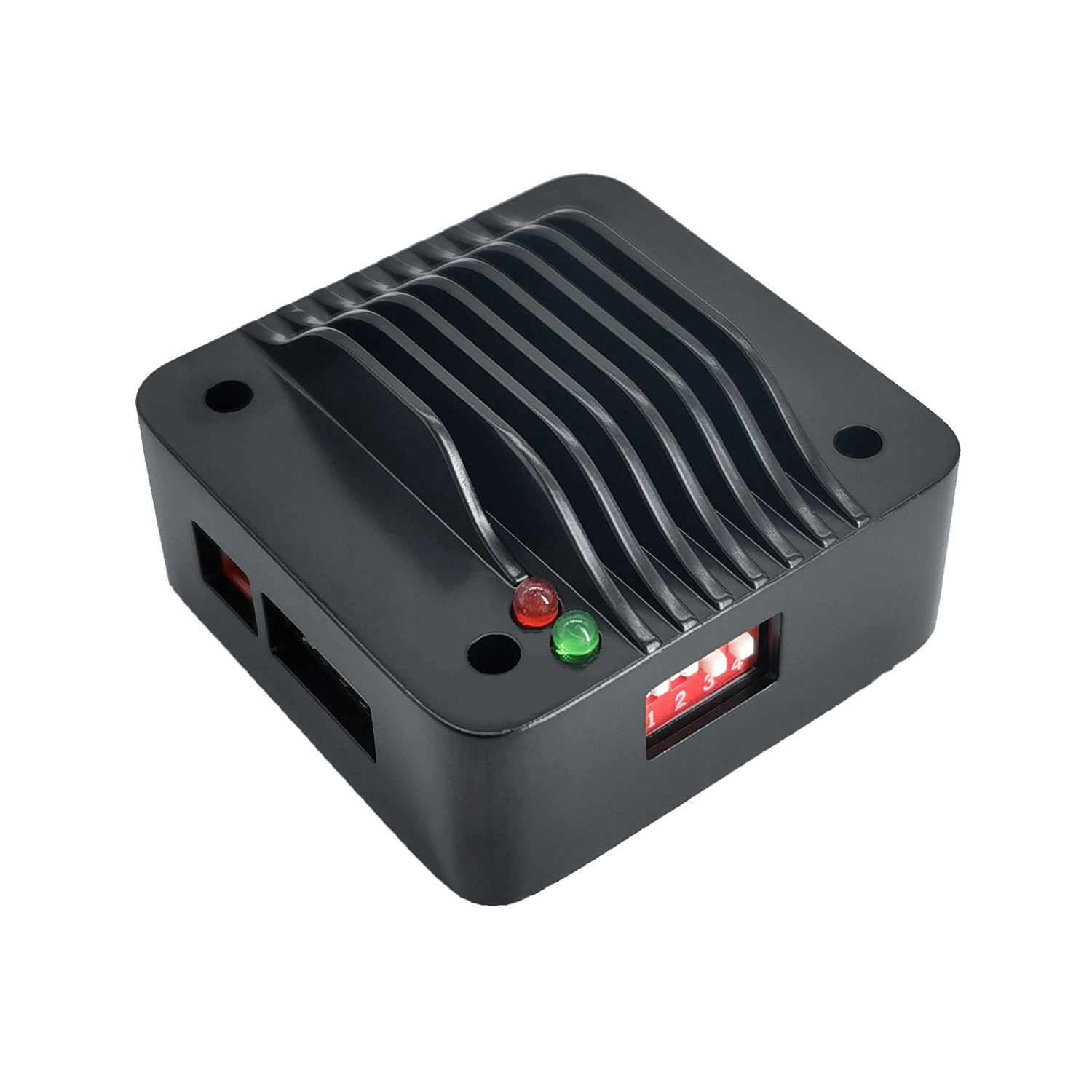
PMD006
√ wide range of 9~48v single voltage supply
√ output current 0.3~6A, which can be adjusted continuously
√ support common anode, common cathode, differential, double pulse, pulse direction, and other input modes
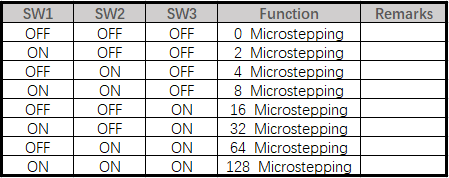
√ support 0/2/4/8/16/32/64/128 microstepping accuracy
√ support 4/6/8 lines of 2-phase stepper motor
√ TSD\UVLO\OCP protection
Main characteristics
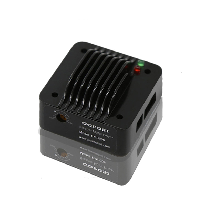
PMD006 is a micro two-phase stepping motor driver, which can be directly installed on the back cover of 42/57/86 motor. It has the characteristics of small size, strong driving force and low calorific value. PMD006 stepper motor driver can provide 0-6A continuous adjustable peak current, maximum 128 micro step, idle current continuous adjustable.
Technical data
General
|
PMD006 Pulse Series
|
|
| Development environment |
PLC .MCU
|
| Support motor |
2-phase stepper motor
|
| The power supply voltage |
DC9-48V
|
| Output Current |
DC0.3-6A
|
| Microstepping |
0/128 adjustable
|
| Temp.Range |
-40℃~80℃
|
| Maximum pulse frequency |
250K
|
| Durability |
Over 20,000 hours
|
Weight |
47g
|
The interface definition
| Interface |
PMD006 Pulse Series
|
| J1 |
ENA+-:Enable signal, optocoupler input, not enable on conduction
PUL+-:Pulse signal, optocoupler input DIR+-:Direction (or pulse) signal, optocoupler input The interface voltage:5V |
| J2 |
M10,M11:Step motor A phase
M20,M21:stepper motor B phase |
| J3 |
VCC:DC power supply
GND:Ground |
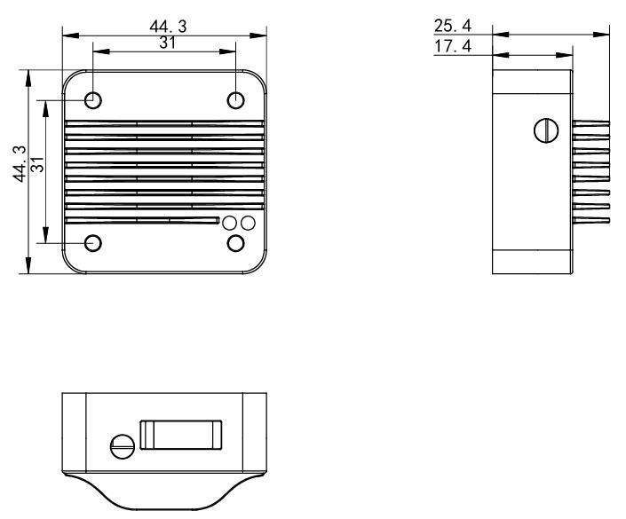
Demension
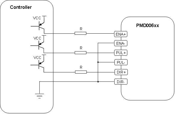
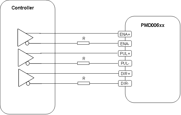
Signal port connection mode
| Connection |
Wiring diagram (when the output voltage of the controller is within 5V, the resistance R can be omitted)
|
| Common anode |
This connection current flows in from the driver's + port, out from the signal-port, and into the controller's ground
|
| Common cathode |
This connection is suitable for connecting controller OC/OD output

|
| The differential connection |
This kind of connection method is suitable for long line connection in harsh environment, and can significantly improve the signal transmission distance and anti-interference ability
|
Download
| CAD |
Micro stepping motor driver PMD006.DWG
|
| The 3 d file |
Micro stepping motor driver PMD006.STP
|
| The user manual | |
| Debug software |
None
|
| Development of the document |
None
|
| Certificate |
|
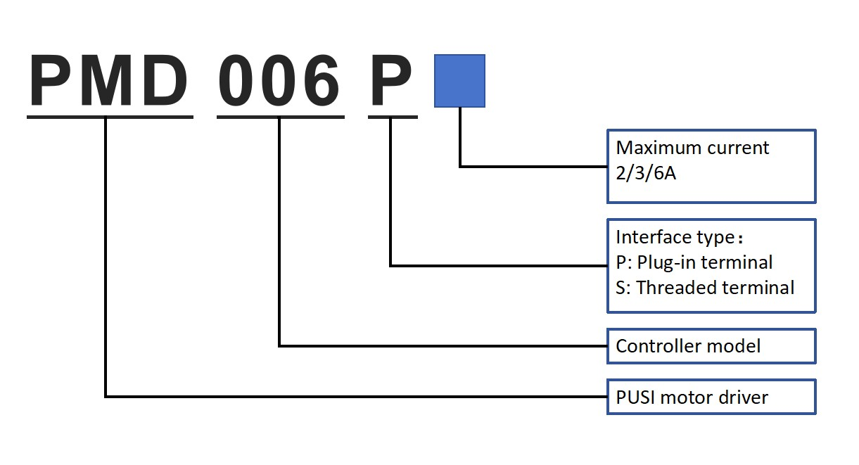
Selection guide
Functional features
| Function |
Describe
|
| Maximum 128 microstepping |
Maximum support 128 adjustable microstepping
|
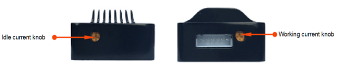
| External adjustment of working/idle current |
The driver supports the external knob mode to adjust the working current and idle current
|